True triaxial real-time scanning CT test device and method for high-pressure hard rock fracture process

A test device, true triaxial technology, applied in the direction of measuring device, applying stable tension/pressure to test material strength, instruments, etc., can solve the problem of not being able to meet the requirements of direct observation of deep brittle hard rock and the real-time failure of deep rock mass rupture Scanning requirements and other issues to achieve the effect of meeting the requirements of direct observation

Active Publication Date: 2021-03-16
NORTHEASTERN UNIV +1
View PDF8 Cites 1 Cited by
  • Summary
  • Abstract
  • Description
  • Claims
  • Application Information

AI Technical Summary

Problems solved by technology

[0004] The high-energy accelerator CT rock mechanics test system developed in recent years, although it meets the loading and scanning requirements of rocks under uniaxial compression and conventional triaxial compression conditions, it still cannot meet the requirements of deep rock mass rupture under true triaxial stress loading conditions. Real-time scanning requirements for the whole process
[0005] For the fracture test research of deep rock mass under true triaxial stress state, scholars have developed different types of true triaxial loading testing machines

Method used


Image

  • True triaxial real-time scanning CT test device and method for high-pressure hard rock fracture process
  • True triaxial real-time scanning CT test device and method for high-pressure hard rock fracture process
  • True triaxial real-time scanning CT test device and method for high-pressure hard rock fracture process

Examples


Embodiment Construction

[0042] The present invention will be further described in detail below in conjunction with the accompanying drawings and specific embodiments.

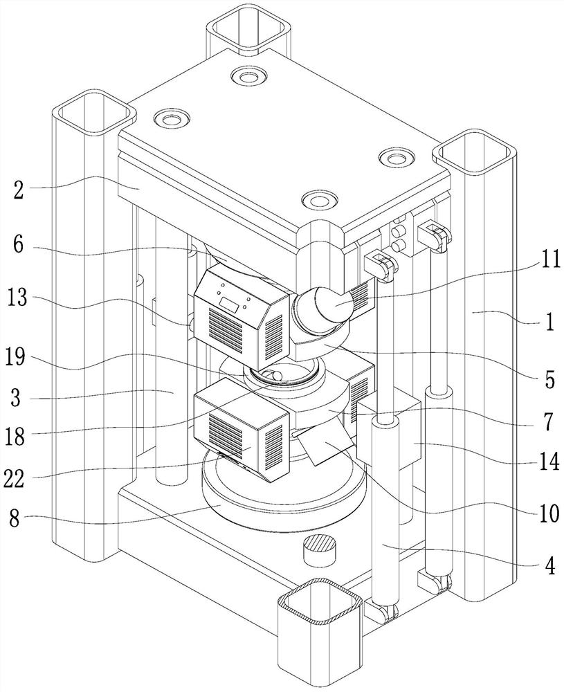
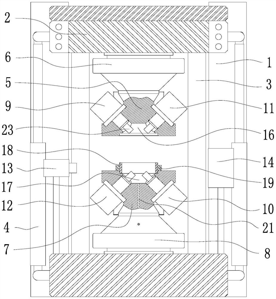
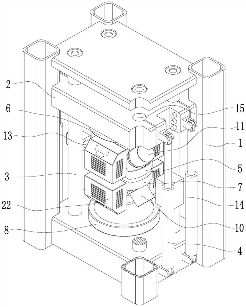
[0043] like Figure 1~4 As shown, a true three-axis real-time scanning CT test device for high-pressure hard rock fracture process, including a rigid frame 1, a rigid beam 2, a beam lifting guide column 3, a beam lifting drive cylinder 4, an upper loading base 5, and an upper base rotation The driving platform 6, the lower loading base 7, the lower base rotary driving platform 8, the first major principal stress actuator 9, the second major principal stress actuator 10, the first middle principal stress actuator 11, the second The main stress actuator 12, the high-energy accelerator CT ray source 13 and the high-energy accelerator CT detection source 14; the lower base rotary drive platform 8 is horizontally installed on the upper surface of the base of the rigid frame 1, and the lower loading base 7 is vertically Directly installed ...


PUM


Abstract

The invention discloses a true triaxial real-time scanning CT (Computed Tomography) test device and method for a high-pressure hard rock fracture process. The device comprises a rigid frame, a rigid cross beam, a cross beam lifting guide vertical column, a a cross beam lifting driving oil cylinder, upper and lower loading bases, upper and lower base rotary driving platforms, a high-energy accelerator CT ray source, a high-energy accelerator CT detection source, and four actuators, wherein the upper loading base and the lower loading base are each provided with two actuators, the four actuatorsare integrally distributed in a 45-degree inclined mode, a supporting cylinder is matched between the upper loading base and the lower loading base to form a pressure chamber, the pressure chamber islocated between the CT ray source and the detection source, and the pressure chamber can horizontally rotate by 360 degrees. The method comprises the following steps of: preparing a sample assembly,scanning the vacant pressure chamber through CT equipment, and providing reference data for subsequent image processing; placing the sample assembly in the pressure chamber, and controlling the rigidcross beam to descend until the pressure chamber is closed; centering and clamping the sample assembly, rotating the pressure chamber, and acquiring a three-dimensional image of the sample through theCT equipment; and applying a true triaxial stress, rotating the pressure chamber, and acquiring three-dimensional images of the sample under various stress conditions through the CT equipment.

Description

technical field [0001] The invention belongs to the technical field of rock mechanics, and in particular relates to a true triaxial real-time scanning CT testing device and method in the high-pressure hard rock fracture process. Background technique [0002] With the continuous development of social and economic construction, there are more and more deep rock mass projects, and the deep rock mass has the characteristics of "three highs and one disturbance", that is, the deep rock mass is in a complex geological environment with high ground stress, high ground temperature and high osmotic pressure. When the deep rock mass is disturbed by engineering excavation, the initial stress state changes, and the local stress concentration causes the deformation and rupture of the rock mass. Therefore, describing the change characteristics of the three-dimensional structure inside the rock mass under the true triaxial stress state and clarifying the deformation and fracture mechanism un...

Claims


Application Information

Patent Timeline
IPC IPC(8): G01N3/06G01N3/12
CPCG01N3/06G01N3/12G01N2203/0003G01N2203/0019G01N2203/0048G01N2203/0256G01N2203/0617G01N2203/0647
Inventor 冯夏庭段永婷张希巍马东辉杨成祥
Owner NORTHEASTERN UNIV
Why Eureka
Try Eureka