Gland structure for optical fiber fusion splicer

An optical fiber fusion splicer and capping technology, which is applied to the coupling of optical waveguides, light guides, optics, etc., can solve the problems of difficult cleaning, cumbersome operation, and large opening area, and achieve the effect of reducing the steps of fusion and improving the functionality.

Pending Publication Date: 2021-03-16
海泰伲克(天津)实业有限公司
View PDF0 Cites 0 Cited by
  • Summary
  • Abstract
  • Description
  • Claims
  • Application Information

AI Technical Summary

Problems solved by technology

[0003] The traditional welding machine gland has the following disadvantages in use: 1. The traditional gland is connected to the body through a rotating shaft, and the opening method is direct opening, and the opening area is relatively large. Large openings can easily cause dust and impurities to fall into the top of the body, making it difficult to clean; 2. The traditional gland has a single function and only has basic opening and closing functions. In actual use, it is necessary to use a fixing device to fix the optical fiber inserted into the bottom of the gland. Fixed, cumbersome operation, for this reason, we propose a gland structure for optical fiber fusion splicer

Method used


Image

  • Gland structure for optical fiber fusion splicer
  • Gland structure for optical fiber fusion splicer

Examples


Embodiment Construction

[0018] In order to make the purpose, technical solution and advantages of the present invention clearer, the present invention will be further described in detail below in conjunction with the accompanying drawings. Apparently, the described embodiments are only some of the embodiments of the present invention, rather than all of them. Based on the embodiments of the present invention, all other embodiments obtained by persons of ordinary skill in the art without making creative efforts belong to the protection scope of the present invention.

[0019] The following will combine Figure 1 to Figure 2 A gland structure for an optical fiber fusion splicer according to an embodiment of the present invention will be described in detail.

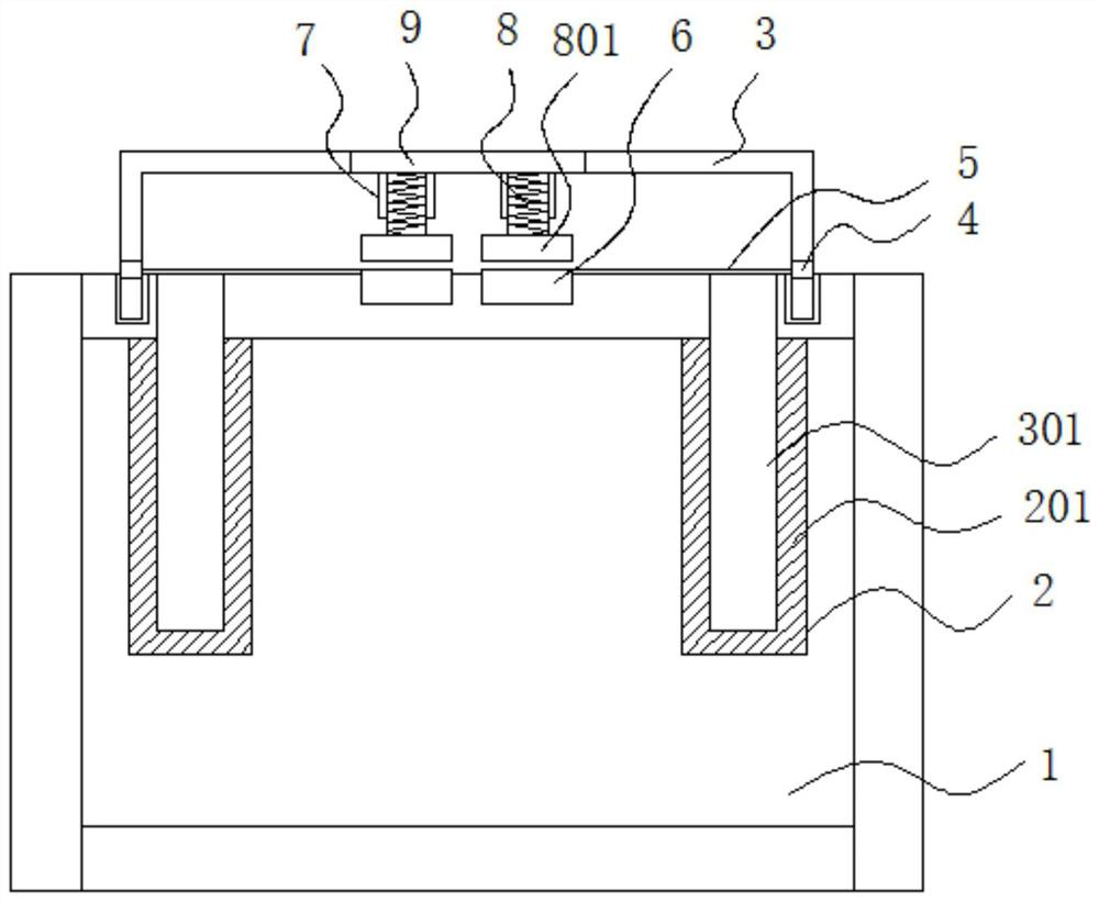
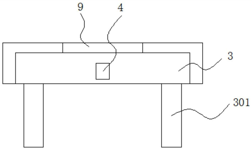
[0020] refer to figure 1 and figure 2 As shown, a gland structure for an optical fiber fusion splicer provided by the embodiment of the present invention includes a body 1, and the inside of the body 1 is provided with four insertion holes 2 an...


PUM


Abstract

The invention discloses a gland structure for an optical fiber fusion splicer, which belongs to the technical field of optical fiber fusion splicers. The gland structure comprises a machine body, fourinsertion holes are formed in the machine body, a gland is detachably connected to the top of the machine body, and insertion columns inserted into the insertion holes are fixedly connected to the bottom of the gland. Through holes are formed in the two sides of the surface of the gland, two lower clamping blocks are fixedly connected to the top of the machine body, and when optical fibers need to be welded, the gland is pulled upwards along the insertion holes, so that the gland moves upwards, and at the moment, the exposed positions of the through holes are gradually increased; optical fibers needing to be welded are inserted into the top of the machine body from the through holes in the two sides respectively, then the gland is pressed down to be closed, only the through holes are communicated with the inside and the outside when the gland is opened, the opening area is reduced, and then the purpose of reducing dust entering is achieved.

Description

technical field [0001] The invention relates to the technical field of optical fiber fusion splicers, in particular to a gland structure for an optical fiber fusion splicer. Background technique [0002] Optical fiber fusion splicer is mainly used for the construction and maintenance of optical cables in optical communication, so it is also called optical cable fusion splicer. The general working principle is to use high-voltage arc to melt the two optical fiber sections and at the same time use high-precision motion mechanism to gently push the two optical fibers into one. , in order to realize the coupling of the fiber mode field, the fusion splicer gland is the cover installed on the top of the fusion splicer. [0003] The traditional welding machine gland has the following disadvantages in use: 1. The traditional gland is connected to the body through a rotating shaft, and the opening method is direct opening, and the opening area is relatively large. Large openings can...

Claims


Application Information

Patent Timeline
Patent Type & Authority Applications(China)
IPC IPC(8): G02B6/255
CPCG02B6/2551G02B6/2553
Inventor 易佳胜白海军
Owner 海泰伲克(天津)实业有限公司
Why Eureka
Try Eureka