Antenna and electronic equipment

A technology for electronic equipment and antennas, applied in the direction of antenna, antenna grounding switch structure connection, electrical components, etc., can solve the problem of too many antennas, and achieve the effect of reducing cost, widening radiation bandwidth, and reducing the number of antennas

Active Publication Date: 2021-03-16
BEIJING BYTEDANCE NETWORK TECH CO LTD
View PDF8 Cites 0 Cited by
  • Summary
  • Abstract
  • Description
  • Claims
  • Application Information

AI Technical Summary

Problems solved by technology

[0003] Aiming at the shortcomings of the existing methods, this application proposes an antenna and electronic equipment to

Method used


Image

  • Antenna and electronic equipment
  • Antenna and electronic equipment
  • Antenna and electronic equipment

Examples


Embodiment Construction

[0029] The present application is described in detail below, and examples of embodiments of the present application are shown in the drawings, wherein the same or similar reference numerals denote the same or similar components or components having the same or similar functions throughout. Also, detailed descriptions of known technologies will be omitted if they are not necessary to illustrate the features of the present application. The embodiments described below by referring to the figures are exemplary only for explaining the present application, and are not construed as limiting the present application.

[0030] Those skilled in the art can understand that, unless otherwise defined, all terms (including technical terms and scientific terms) used herein have the same meanings as commonly understood by those of ordinary skill in the art to which this application belongs. It should also be understood that terms, such as those defined in commonly used dictionaries, should be ...


PUM


Abstract

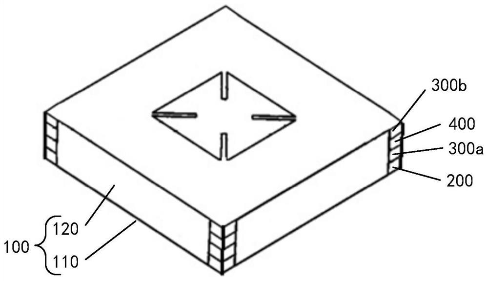
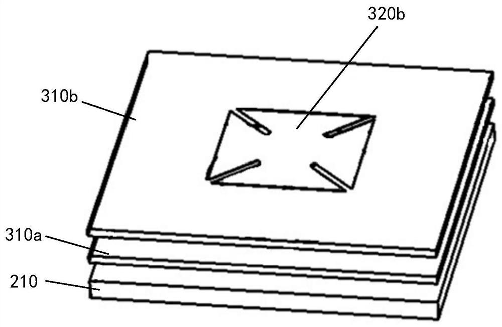
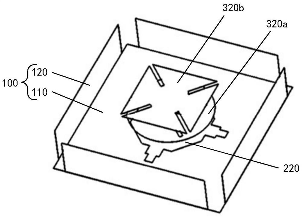
The embodiment of the invention provides an antenna and electronic equipment. The antenna comprises a substrate, and a reflecting plate, a radiation layer and at least one coupling layer which are insulated from one another and are sequentially laminated on one side of the substrate, wherein the reflection plate is made of a metal material and is used for grounding, the radiation layer comprises aradiation substrate and a radiation structure which are stacked in sequence, the radiation substrate is located on one side, away from the substrate, of the reflection plate, the radiation structureis located at one side of the radiation substrate away from the reflection plate, the radiation structure is provided with at least two feed ports, the projections of the at least two feed ports on the radiation substrate are orthogonally arranged, and the radiation structure is coupled with the at least one coupling layer through electromagnetic radiation. According to the embodiment of the invention, the radiation bandwidth of a single antenna module can be effectively broadened, so that the number of antennas in the communication equipment can be effectively reduced, the cost can be reduced, the space occupation of the communication equipment by the antennas can be reduced, and the miniaturization design of the communication equipment is facilitated.

Description

technical field [0001] The present application relates to the technical field of antennas, and in particular, the present application relates to an antenna and an electronic device. Background technique [0002] With the popularization and development of smart terminal equipment, especially the arrival of 5G communication, the number of communication frequency bands and antennas of smart terminals has greatly increased, and the design difficulty of antennas has greatly increased, especially the layout of small smart terminals is very compact, and 2 / 3 / 4 / 5G (where n G represents nthgeneration mobile communication technology, that is, nth generation mobile communication technology) communication antennas, GPS (Global Positioning System, Global Positioning System), WiFi (wireless broadband or wireless network) antennas are designed on the terminal, challenging the difficulty very big. For example, the number of antennas on a metal mobile phone increases, and more broken seams ...

Claims


Application Information

Patent Timeline
IPC IPC(8): H01Q1/38H01Q1/50H01Q15/14
CPCH01Q1/38H01Q15/14H01Q1/50
Inventor 郭海鹏万逢毅张魁许安民
Owner BEIJING BYTEDANCE NETWORK TECH CO LTD
Why Eureka
Try Eureka