Power switch cabinet

A technology for power switches and cabinets, which is applied in the field of switch cabinets, which can solve the problems of dust entering the cabinet, heat dissipation process relying on exhaust fans, and high cost of dust cleaning operations, so as to achieve the effect of ensuring dust-proof protection and good dust-proof protection

Inactive Publication Date: 2021-03-16
郎启云
View PDF1 Cites 3 Cited by
  • Summary
  • Abstract
  • Description
  • Claims
  • Application Information

AI Technical Summary

Problems solved by technology

[0004] Although this switchgear solves the problems existing in the traditional switchgear to a certain extent, it still has the following disadvantages: the operation cost of dust cleaning is relatively high, and the heat dissipation process is too dependent on the

Method used


Image

  • Power switch cabinet
  • Power switch cabinet
  • Power switch cabinet

Examples


Embodiment 1

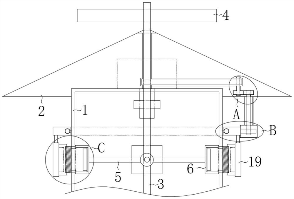
[0028] refer to Figure 1-3 , an electric switchgear, comprising a cabinet body 1, a rain-shielding frame 2, a driving shaft 3 is installed in rotation between the cabinet body 1 and the rain-shielding frame 2, and the upper end of the driving shaft 3 runs through the rain-shielding frame 2 and is fixedly installed with a fan Leaf 4, a plurality of connecting rods 5 are fixedly installed on the driving shaft 3, and a shielding plate 6 is fixedly installed on the end of each connecting rod 5 away from the driving shaft 3;

[0029] Above-mentioned noteworthy is: offer the through hole that cooperates with driving shaft 3 on the rain-shielding frame 2, and the inner wall of the through-hole is fixedly installed with sealing ring; The fit is more stable, and at the same time avoids the occurrence of water leakage.

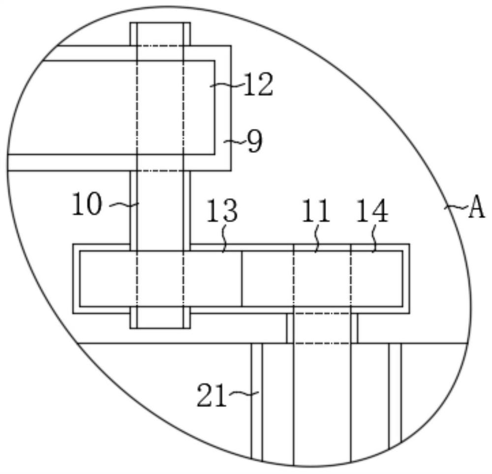
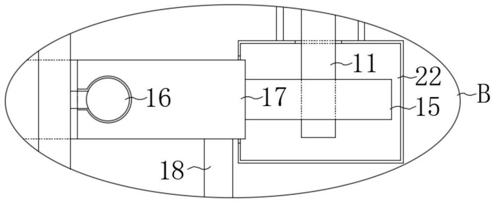
[0030] A plurality of installation covers 7 are threadedly installed on the cabinet body 1, and the installation covers 7 are hollow structures connected at both ends...

Embodiment 2

[0044] refer to figure 1 , Figure 4 , the difference between this embodiment and Embodiment 1 is that a square chute 23 is provided on the side of each shielding plate 6 away from the connecting rod 5, and a magnetic plate 24 is slidably installed in each square chute 23 , the magnetic plate 24 is fixedly installed with two brushes 25 near the side of the cabinet body 1, and two magnetic blocks 26 are fixedly installed on each mounting block 19, and the magnetism between the corresponding two magnetic blocks 26 is opposite, and the shielding plate 6 The length is twice the length of the mounting block 19, and the brush one 20 is installed between the two magnetic blocks 26.

[0045]During the rotation process, the magnetic block 26 first produces an attractive force to the magnetic plate 24, and utilizes the attractive force to drive the magnetic plate 24 and the second hair brush 25 to move toward the side close to the filter screen 8, thereby utilizing the second hair brus...


PUM


Abstract

The invention discloses a power switch cabinet which comprises a cabinet body and a rain shielding frame; a driving shaft is rotatably installed between the cabinet body and the rain shielding frame,the upper end of the driving shaft penetrates through the rain shielding frame and is fixedly provided with fan blades, the rain shielding frame is provided with a through hole matched with the driving shaft, and the inner wall of the through hole is fixedly provided with a sealing ring; a plurality of connecting rods are fixedly installed on the driving shaft, and a shielding plate is fixedly installed at the end, away from the driving shaft, of each connecting rod; a plurality of mounting covers are installed on the cabinet body in a threaded mode, each mounting cover is of a hollow structure with the two ends communicated, and a filter screen is fixedly installed at the end, away from the cabinet body, of each mounting cover. The cabinet has the advantages that the flowing of natural gas is used as a power source to clean dust intercepted on the filter screen, so that the ventilation and heat dissipation effects of the filter screen are ensured, and meanwhile, the probability that the dust enters the cabinet body in the cleaning process is effectively reduced through the cooperation of the baffle plate in the dust cleaning process.

Description

technical field [0001] The invention relates to a switch cabinet, in particular to a power switch cabinet. Background technique [0002] The power switchgear is used to control and protect the electrical equipment used in the power system. Circuit breakers, isolating switches, load switches, etc. are installed in it; the traditional power switchgear is used to ensure that the power switch To improve the heat dissipation effect of the cabinet, it is necessary to manually clean the dust on the heat dissipation net regularly, which has the problems of slow speed and low efficiency. [0003] After retrieval, the Chinese authorized invention patent with the patent number CN105305251B discloses a power switch cabinet, including a cabinet body, cabinet doors are provided on both sides of the cabinet body, and handles are provided on the front surface of the cabinet door. A rain shelter is fixedly installed on the top of the cabinet, an air storage tank is arranged inside the rain ...

Claims


Application Information

Patent Timeline
IPC IPC(8): H02B1/28H02B1/32B08B1/04F03D9/34F03D15/00
CPCB08B1/002B08B1/04F03D9/34F03D15/00H02B1/28H02B1/32Y02E10/72Y02E10/728
Inventor 郎啟云
Owner 郎启云
Why Eureka
Try Eureka