Groove-type rare earth permanent magnet brushless motor

A rare-earth permanent magnet and brushless motor technology, which is applied in the direction of electrical components, electromechanical devices, electric components, etc., can solve problems such as failure to issue alarms in time, motor damage, and potential safety hazards, so as to prevent damage from long-term overspeed rotation and improve use. Longevity, easy and timely processing effect

Active Publication Date: 2021-03-16
SUMEC HARDWARE & TOOLS
View PDF6 Cites 5 Cited by
  • Summary
  • Abstract
  • Description
  • Claims
  • Application Information

AI Technical Summary

Problems solved by technology

[0003] When the motor is working, due to changes in the working environment and work needs, the motor speed needs to be changed frequently. The current permanent magnet brushless motor usually controls the motor speed through the controller to control the current. Frequent changes in the motor current by the controller are likely to cause damage to the motor. , and at present, when the motor is turned on, a large current will have a greater impact on the motor, which increases the probability of motor damage, and at present, when the motor is stopped, it is usually directly controlled by the controller to power off the motor, and the rotor is directly powered off due to inertia It will still rotate for a long time, and direct power failure will cause great damage to the motor. In addition, the existing motor usually does not have a monitoring device. When the motor rotates too fast, an alarm cannot be issued in time, which has certain potential safety hazards. A slot type rare earth permanent magnet brushless motor to solve the problems raised above

Method used


Image

  • Groove-type rare earth permanent magnet brushless motor
  • Groove-type rare earth permanent magnet brushless motor
  • Groove-type rare earth permanent magnet brushless motor

Examples


Embodiment Construction

[0024] The following will clearly and completely describe the technical solutions in the embodiments of the present invention with reference to the accompanying drawings in the embodiments of the present invention. Obviously, the described embodiments are only some, not all, embodiments of the present invention.

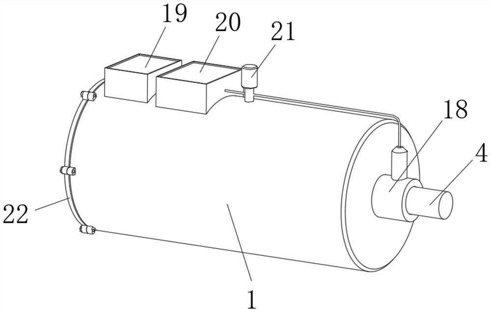
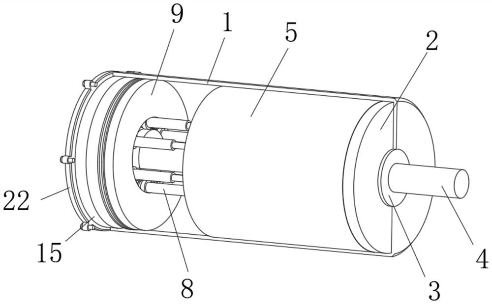
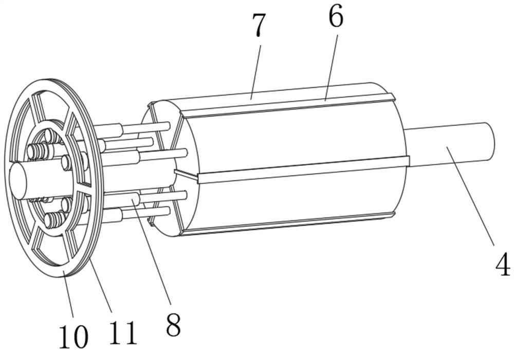
[0025] see Figure 1 to Figure 7, the present invention provides a technical solution: a slot-type rare earth permanent magnet brushless motor, including a motor housing 1, a right side bearing support 2 is fixedly installed on the right side inside the motor housing 1, and the right side bearing support 2 The middle fixed sleeve has a ball bearing 3, the middle fixed sleeve of the ball bearing 3 has a drive shaft 4, the inner fixed sleeve of the motor housing 1 has a stator 5, and the inside of the stator 5 is wound with a winding wire 13, and the external fixed installation of the drive shaft 4 is limited. The limit splint 6, and the inside of the limit splint 6 is...


PUM


Abstract

The invention discloses a groove-type rare earth permanent magnet brushless motor, and relates to the technical field of brushless motors, in particular to a groove-type rare earth permanent magnet brushless motor which comprises a motor shell. A right side bearing support is fixedly installed on the right side in the motor shell, a ball bearing is fixedly installed in the middle of the right sidebearing support in a sleeving mode, and the middle of the ball bearing is fixedly sleeved with a driving shaft. According to the groove-type rare earth permanent magnet brushless motor, a micro controller controls a plurality of micro electric telescopic rods to drive a magnet rotor to move, and the effective contact length of the magnet rotor, a stator and a winding wire is adjusted, so that therotating speed of the motor is adjusted, the problem that the motor is easily damaged due to frequent adjustment of current in the prior art is solved, the service life of the motor is improved, andmeanwhile, through mutual cooperation of a limiting clamping ring and a limiting bearing, the miniature electric telescopic rods are limited, and the stability of the miniature electric telescopic rods driven by the magnet rotor to rotate is guaranteed.

Description

technical field [0001] The invention relates to the technical field of brushless motors, in particular to a slot-type rare earth permanent magnet brushless motor. Background technique [0002] A permanent magnet brushless motor is a permanent magnet motor that is commutated or current controlled by an electronic circuit. There are two types of permanent magnet brushless motors: sine wave drive and square wave drive; the driving current is a rectangular wave is usually called a permanent magnet brushless DC motor, and the driving current is a sine wave is usually called a permanent magnet AC servo motor. Induction types can be divided into sensor motors and positive sensor motors. Compared with electric excitation motors, permanent magnet motors, especially rare earth permanent magnet motors, have simple structure, reliable operation, small size, light weight, low loss, and high efficiency; The shape and size can be flexible and various, so the application range is extremely...

Claims


Application Information

Patent Timeline
Patent Type & Authority Applications(China)
IPC IPC(8): H02K7/12H02K11/30H02K11/21H02K29/14H02K5/22H02K5/173
CPCH02K7/12H02K11/30H02K11/21H02K29/14H02K5/225H02K5/1732H02K2211/03
Inventor 刘楷林有余吴玉华周国扬
Owner SUMEC HARDWARE & TOOLS
Why Eureka
Try Eureka