Check patentability & draft patents in minutes with Patsnap Eureka AI!

Configuration method and device, binding method and device, equipment, sending node, receiving node and medium

A technology for sending nodes and receiving nodes, applied in equipment, binding methods, devices, receiving nodes and media, configuration, and sending fields. Low reliability of layer channel and optical layer channel multiplexing

Pending Publication Date: 2021-03-16
ZTE CORP
View PDF0 Cites 1 Cited by
  • Summary
  • Abstract
  • Description
  • Claims
  • Application Information

AI Technical Summary

Problems solved by technology

However, the optical media layer multiplexing standard does not involve sub-channels and the correspondence between sub-channels and physical interfaces. The overhead information composition method of the optical media layer is not suitable for the FlexO signal format defined by the OTN interface standard, and cannot distinguish between different OTSi The signals are encapsulated separately, and it cannot provide enough information to support multiplexing and demultiplexing of OTUCn signals
Because the multiplexing of optical layer channels cannot be effectively configured, the binding of optical channels or the creation of optical layer paths cannot be accurately realized, and the multiplexing reliability of optical layer channels is low.

Method used


Image

  • Configuration method and device, binding method and device, equipment, sending node, receiving node and medium
  • Configuration method and device, binding method and device, equipment, sending node, receiving node and medium
  • Configuration method and device, binding method and device, equipment, sending node, receiving node and medium

Examples


Embodiment Construction

[0059] The application will be described below in conjunction with the accompanying drawings and embodiments. It should be understood that the specific embodiments described here are only used to explain the present application, but not to limit the present application. It should be noted that, in the case of no conflict, the embodiments in the present application and the features in the embodiments can be combined arbitrarily with each other. In addition, it should be noted that, for the convenience of description, only some structures related to the present application are shown in the drawings but not all structures.

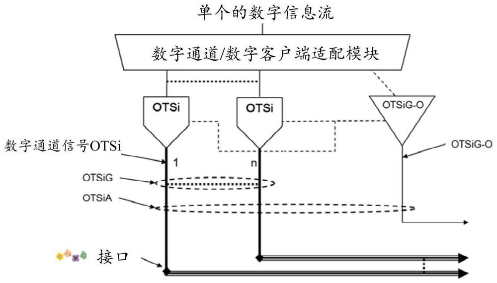
[0060] In the process of mapping the client signal to the optical medium layer for transmission, the multiplexing standard of the optical medium layer does not involve the sub-channels of the optical layer channel and the correspondence between the sub-channels and the physical interface, and the composition method of the header overhead information of the op...


PUM


Abstract

The invention provides a configuration and binding method and device, equipment, a sending node, a receiving node and a medium. The method comprises the steps of determining a multiplexing structure of an optical layer channel; and configuring channel identification information for a target node according to the multiplexing structure, wherein the channel identification information is used for indicating the target node to bind an optical layer channel.

Description

technical field [0001] The present application relates to optical fiber communication, for example, to a configuration and binding method, device, equipment, sending and receiving nodes and media. Background technique [0002] Optical fiber communication has the characteristics of high bandwidth, long transmission distance, and low loss. It has been deployed on a large scale. The electrical-layer customer signal stream can be multiplexed into optical-layer signals for transmission. A fully standardized Optical Transport Unit-Cn (CompletelyStandardized Optical Transport Unit-Cn, OTUCn) signal can be divided into multiple flexible optical transport network (Flexible Optical Transport Network, FlexO) physical channels, and each FlexO physical channel can be divided into multiple sub-channels , each sub-channel is transmitted through a separate Optical Time Slot Interchanger (OTSi) signal, corresponding to a single physical interface, and the wavelength center of the OTSi signal...

Claims


Application Information

Patent Timeline
IPC IPC(8): H04Q11/00
CPCH04Q11/0067H04Q2011/0079H04Q2011/0086H04J3/1652H04J14/0258
Inventor 王其磊
Owner ZTE CORP
Features
  • R&D
  • Intellectual Property
  • Life Sciences
  • Materials
  • Tech Scout
  • Unparalleled Data Quality
  • Higher Quality Content
  • 60% Fewer Hallucinations
Learn More