Method for automated electronic control of brake system in utility vehicle having Anti-lock braking protection

An electronic control and braking system technology, applied in the field of pneumatic braking systems and vehicles, can solve problems such as redundancy, and achieve the effects of improving stability, preventing axle locking and preventing locking.

Active Publication Date: 2021-03-16
WABCO GMBH
View PDF8 Cites 0 Cited by
  • Summary
  • Abstract
  • Description
  • Claims
  • Application Information

AI Technical Summary

Problems solved by technology

In this case, a redundant situation occurs, in particular if the elec...

Method used


Image

  • Method for automated electronic control of brake system in utility vehicle having Anti-lock braking protection
  • Method for automated electronic control of brake system in utility vehicle having Anti-lock braking protection

Examples


Embodiment Construction

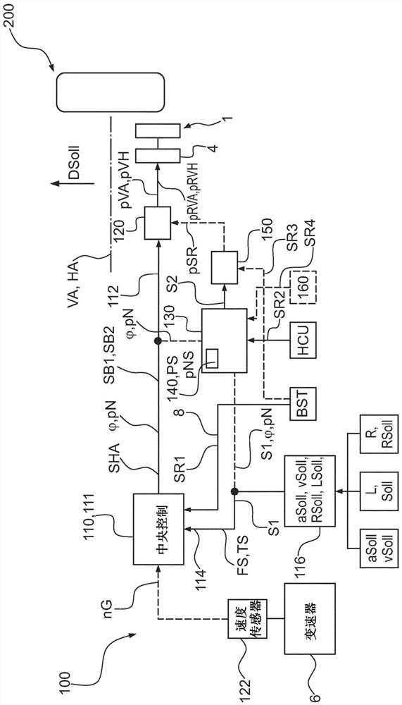
[0049] in accordance with figure 1 In the embodiment of FIG. 1 , a portion of the braking system 100 of a vehicle 200 is shown in a block diagram. Brake system 100 therefore has a first electronic control unit 110 and a first electropneumatic control device 120 . In this exemplary embodiment, the first electronic control unit 110 is designed as a so-called central module 111 and is connected via a first bus 112 to a first electropneumatic control device 120 . First electronic control unit 110 supplies at least one first brake pressure signal SB1 , but preferably also a second brake pressure signal SB2 , via first bus 112 to first electropneumatic control device 120 . The first electropneumatic control device 120 preferably has an electronic control unit (not shown) and one or more valves (not shown), which are used to convert the first brake pressure signal SB1 and preferably the second brake pressure signal SB1 Dynamic pressure signal SB2 is converted into at least front ax...


PUM


Abstract

The invention relates to a method for the automated electronic control of a brake system (100) in a utility vehicle (200), the method comprising the following steps: reading in a brake request signal(S1), wherein via said signal, requests (aSoll, vSoll) to be implemented by brakes (1) are transmitted in order to bring about a vehicle setpoint longitudinal dynamics (DSoll); determining a brake pressure distribution (phi); providing at least one first brake pressure signal (SB1, SB2) from a first electronic control unit (110) at least one first electropneumatic control device (120), taking intoconsideration the brake request signal (S1) and the brake pressure distribution (phi) for controlling the front-axle brake pressure (pVA) and rear-axle brake pressure (pVH ); receiving the brake pressure distribution(phi) at a second electronic control unit (130), and storing the brake pressure distribution (phi S). In the event that the brake request signal (S1) cannot be processed or read in correctly, according to the invention, the brake request signal (S1) or a redundant brake request signal (SR) is received on the second electronic control unit (130), and in response thereto, a redundant front-axle and rear axle brake pressure (pRVA, pRVH) is modulated taking the stored brake pressure distribution (phi S) into consideration.

Description

technical field [0001] The invention relates to a method for automated electronic control of a braking system in a vehicle, in particular a commercial vehicle, in particular in an automated controllable commercial vehicle. The invention also relates to an electronically controllable pneumatic braking system for a vehicle, in particular a commercial vehicle, in particular an automated controllable commercial vehicle, and such a vehicle. Background technique [0002] In vehicles, in particular commercial vehicles, with a pneumatic brake system, in particular designed as an electronic service brake system (EBS), the electronic control unit (ECU) controls the electronic control unit (ECU) in order to regulate the brake pressure Valves, such as relay valves or axle modulators, these electronically controlled valves then pneumatically regulate the brake pressure to the brake cylinders of the service brakes of the braking system as a function of the requested target acceleration of...

Claims


Application Information

Patent Timeline
IPC IPC(8): B60T8/1766B60T8/26B60T8/88B60T13/26B60T13/68
CPCB60T8/1766B60T8/263B60T13/261B60T13/683B60T8/885B60T2270/413B60T8/329B60T8/171B60T8/1761B60T2270/10B60T2270/88
Inventor 克劳斯·普兰朱利安·万蒂勒
Owner WABCO GMBH
Why Eureka
Try Eureka