Concrete pumping pipeline blockage part detection device

A concrete pump and detection device technology, applied in the direction of cleaning hollow objects, cleaning methods and utensils, chemical instruments and methods, etc., can solve the problems of cumbersome operation, poor detection accuracy, and small application range, and achieve simplified operation and high accuracy High, the effect of improving the scope of application

Inactive Publication Date: 2021-03-19
德清圣悦传媒科技有限公司
View PDF6 Cites 0 Cited by
  • Summary
  • Abstract
  • Description
  • Claims
  • Application Information

AI Technical Summary

Problems solved by technology

[0004] Aiming at the deficiencies of the prior art, the present invention provides a concrete pumping pipeline blockage detection device, which solves the problems of cumbersome operation, poor detection accuracy and small application range of the traditional detection method

Method used


Image

  • Concrete pumping pipeline blockage part detection device
  • Concrete pumping pipeline blockage part detection device
  • Concrete pumping pipeline blockage part detection device

Examples


Embodiment 1

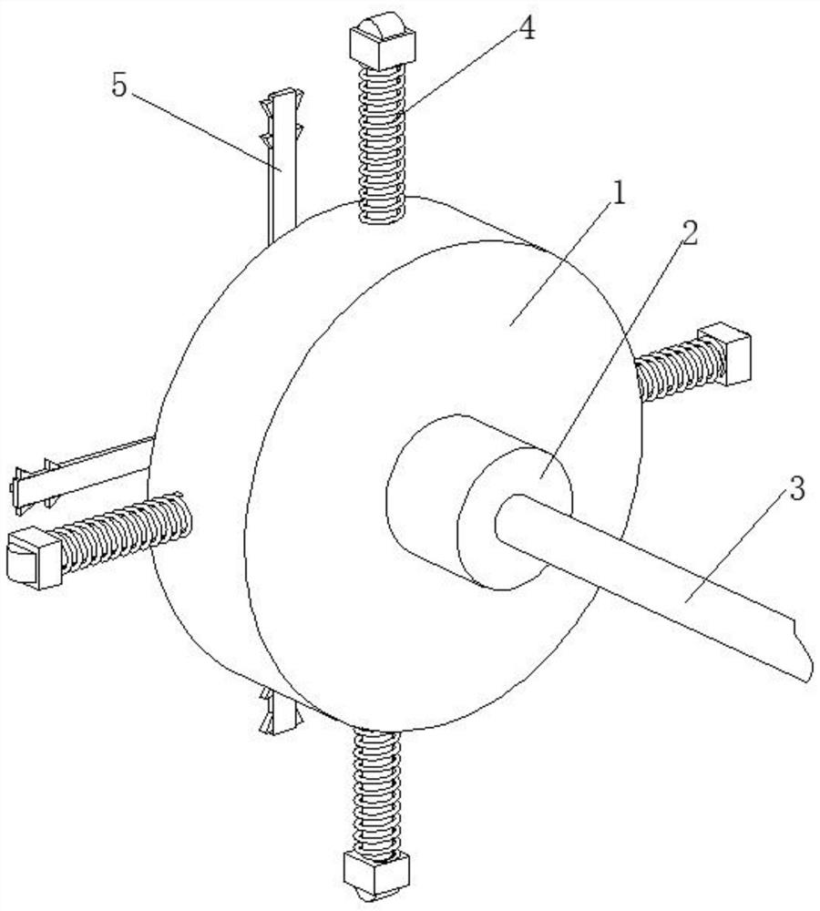
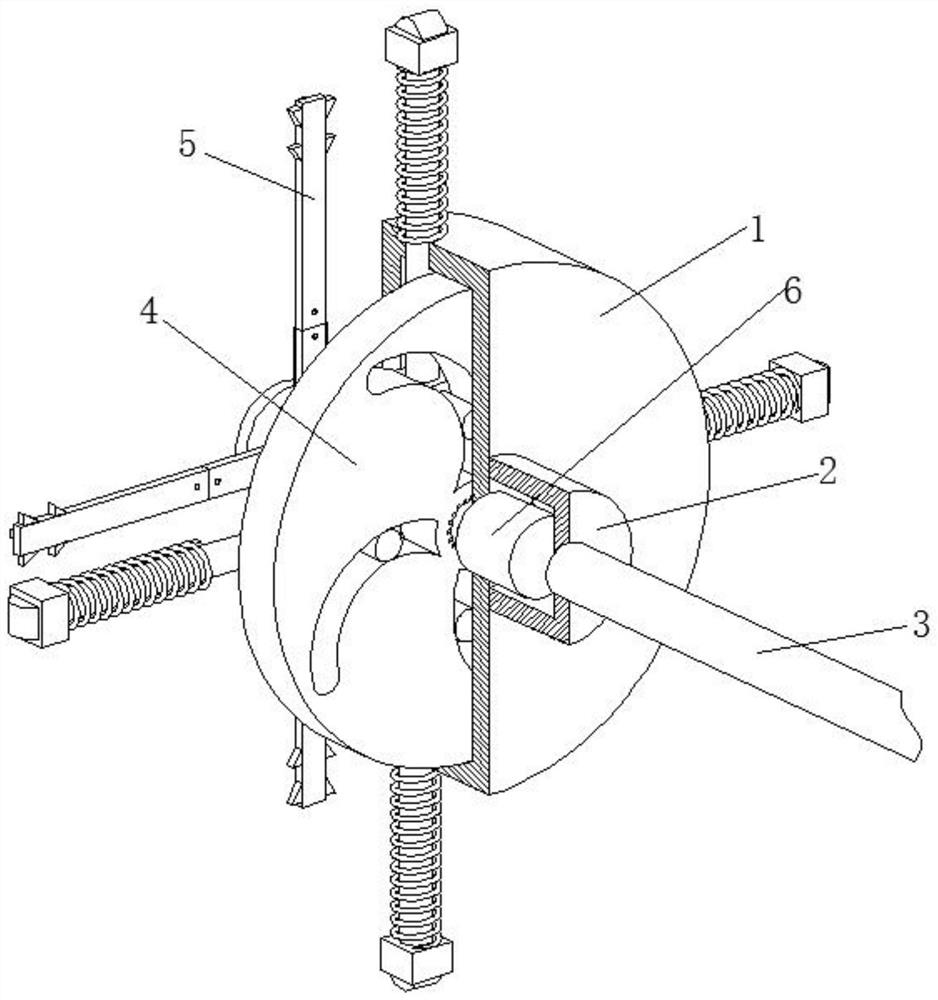
[0031] A concrete pumping pipeline blockage detection device, such as Figure 1-Figure 6 As shown, it includes a fixed plate 1, the right side of the fixed plate 1 is connected with a protective shell 2 by bolts, the right side of the protective shell 2 is connected with a connecting rod 3 by bolts, the inside of the fixed plate 1 is provided with an adjustment mechanism 4, and the fixed plate 1 A dredging mechanism 5 is provided on the left side of the plate, and a motor 6 is connected to the right side of the fixed plate 1 by bolts, and the motor 6 is located inside the protective shell 2 .

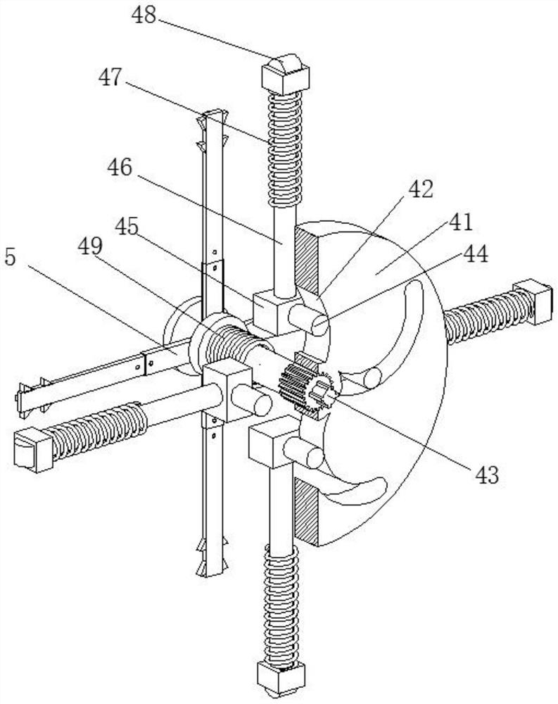
[0032] In this embodiment, the adjustment mechanism 4 includes a turntable 41, and four chutes 42 are arranged inside the turntable 41, and a transmission device 43 is arranged at the axis of the turntable 41, and the inner wall of the chute 42 is movably connected with a clamping rod 44, which The left end of bar 44 is welded with slide block 45, and the top of slide block 45 is welded...

Embodiment 2

[0042] Such as Figure 5-Figure 7As shown, on the basis of Embodiment 1, in this embodiment, the axis of the chuck 51 is welded and fixed to the left end of the sleeve 431, the right side of the chuck 51 is in contact with the left side of the supporting spring 49, and the supporting spring 49 will help the chuck 51 and the shaft sleeve 431 to reset after detecting the blocked part, preventing the motor 6 from driving the turntable 41 to rotate, and then causing the pulley block 48 to rotate inside the pipeline, causing damage to the device and causing the device to fail to continue to operate. Sex is greatly reduced.

[0043] It is worth noting that the crushing device 53 includes a fixed plate 531. Several positioning holes 532 are arranged inside the fixed plate 531. The inner walls of the positioning holes 532 are movably connected with screws 533. The crushing device 53 can remove smaller blockages in the pipeline. By crushing, it is possible to directly dredge the place...


PUM


Abstract

The invention relates to the technical field of concrete processing and detection, and discloses a concrete pumping pipeline blockage part detection device. The concrete pumping pipeline blockage partdetection device comprises a fixing plate, a protective shell is connected to the right side of the fixing plate through a bolt, a connecting rod is connected to the right side of the protective shell through a bolt, an adjusting mechanism is arranged inside the fixing plate, a dredging mechanism is arranged on the left side of the fixing plate, and a motor is connected to the right side of the fixing plate through a bolt. According to the concrete pumping pipeline blockage part detection device, the distance between every two pulleys can be adjusted through a adjusting mechanism, so that theconcrete pumping pipeline blockage part detection device can adapt to pipelines with different diameters, then the practicability is improved, the concrete pumping pipeline blockage part detection device is directly fed into the pipeline through a connecting rod to inspect, then operation is simplified, the accuracy degree is higher, the dredging mechanism can smash smaller blockages in the pipeline and places with lighter blockage in the pipeline can be directly dredged, dredging can be conducted without the need of a pulling-out device, time waste is reduced, and the working efficiency is improved.

Description

technical field [0001] The invention relates to the technical field of concrete processing and detection, in particular to a detection device for a clogged part of a concrete pumping pipeline. Background technique [0002] Concrete refers to the artificial stone made of cement as the main cementitious material, mixed with water, sand, stones, chemical admixtures and mineral admixtures when necessary, mixed in an appropriate proportion, uniformly stirred, compacted and cured. Concrete is mainly divided into two stages and states: the plastic state before setting and hardening, that is, fresh concrete or concrete mixture; the hard state after hardening, that is, hardened concrete or concrete. In concrete, sand and stone play the role of skeleton. Called aggregate; cement and water form a slurry that coats the surface of the aggregate and fills its voids. [0003] At present, a type of detection device can only detect pipes of one diameter, which is not very practical, and the...

Claims


Application Information

Patent Timeline
Patent Type & Authority Applications(China)
IPC IPC(8): B08B9/047
CPCB08B9/047
Inventor 陈强强
Owner 德清圣悦传媒科技有限公司
Why Eureka
Try Eureka