Metal cavity drilling and milling machining chip treatment system

A processing system and metal cavity technology, which is applied in metal processing equipment, metal processing mechanical parts, manufacturing tools, etc., can solve the problems of easy residues of cutting fluid and cutting oil, insufficient chip processing performance, etc., and achieve simple structure and performance. Perfect, structural performance guarantee, guarantee the effect of processing performance

Active Publication Date: 2021-03-19
苏州金锐捷精密五金有限公司
View PDF5 Cites 1 Cited by
  • Summary
  • Abstract
  • Description
  • Claims
  • Application Information

AI Technical Summary

Problems solved by technology

[0004] The purpose of the present invention is to provide a metal cavity drilling and milling processing chip processing system to solve the problem that the existing metal cavity drilling and milling processing chip processing performance is not perfect enough in the above background technology, and more cutting fluid is likely to remain in the chips As well as cutting oil, the problem of not being able to handle it well

Method used


Image

  • Metal cavity drilling and milling machining chip treatment system
  • Metal cavity drilling and milling machining chip treatment system
  • Metal cavity drilling and milling machining chip treatment system

Examples


Embodiment Construction

[0022] The following will clearly and completely describe the technical solutions in the embodiments of the present invention with reference to the accompanying drawings in the embodiments of the present invention. Obviously, the described embodiments are only some, not all, embodiments of the present invention.

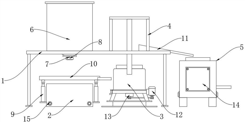
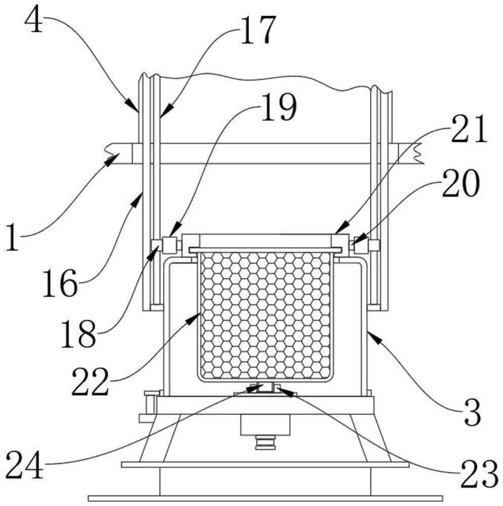
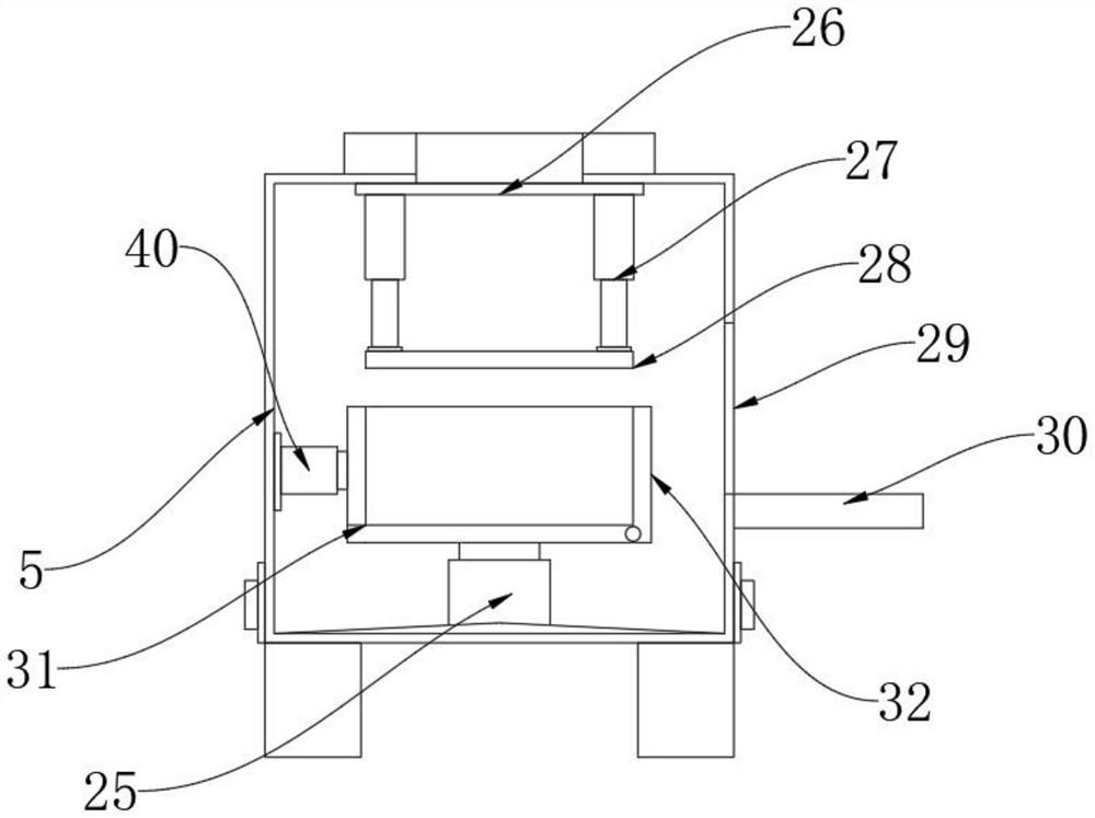
[0023] see Figure 1-5 , an embodiment provided by the present invention: a metal cavity drilling and milling processing chip processing system, including a main support frame 1 of the processing system, a primary oil filter tank 2 is installed on the side below the main support frame 1 of the processing system, and the primary oil filter tank Centrifugal degreasing equipment 3 is installed on one side of 2, briquetting equipment 5 is installed on the other side of centrifugal degreasing equipment 3, chip storage bin 6 is installed on the side above the main support frame 1 of the processing system, and the other side of the chip storage bin 6 An auxiliary working br...


PUM


Abstract

The invention discloses a metal cavity drilling and milling machining chip treatment system, and relates to the technical field of chip treatment. The system aims to solve the problems that at present, metal cavity drilling and milling machining chip treatment performance is not perfect, more chip liquid and chip oil are easily remained in chips, and the chips cannot be well treated. A primary oilfiltering tank is installed on one side below a treatment system main supporting frame, centrifugal oil removing equipment is installed on one side of the primary oil filtering tank, briquetting equipment is installed on the other side of the centrifugal oil removing equipment, and a chip storage bin is installed on one side above the treatment system main supporting frame. An auxiliary working support is installed on the other side of the chip storage bin, electric telescopic rods are installed on the two sides of the primary oil filtering tank, an oil filtering fixing frame is installed above the electric telescopic rods, a guide fixing plate is installed below the inner side of the auxiliary working support, and a fixed connecting sleeve block is installed above the centrifugal oil removing equipment.

Description

technical field [0001] The invention relates to the technical field of chip processing, in particular to a chip processing system for metal cavity drilling and milling. Background technique [0002] The excess material removed during the cutting process is called chips. Chip formation is a complex process, and the chip formation mechanism is different under different conditions, so the chips will show different shapes. When cutting plastic materials, chips are formed due to the shear and slip of the workpiece material, so the shapes of the chips are banded, squeezed, and unit; when processing brittle materials, chips are formed due to the crack expansion in the workpiece, Therefore, its shape is mainly broken chips, but under certain conditions, continuous ribbon or shear chips can also be obtained. [0003] However, the chip treatment performance of the existing metal cavity drilling and milling processing is not perfect, and more cutting fluid and cutting oil tend to rem...

Claims


Application Information

Patent Timeline
Patent Type & Authority Applications(China)
IPC IPC(8): B23Q11/00B01D29/03B01D29/56B01D35/02B01D36/00
CPCB23Q11/0042B01D29/56B01D29/03B01D36/00B01D35/02Y02P70/10
Inventor 张垒
Owner 苏州金锐捷精密五金有限公司
Why Eureka
Try Eureka