
Liftable steel belt reel loading mechanism

A steel strip and reel technology is applied in the field of the loading mechanism of the preloaded high-pressure mold to be wound on the steel reel, which can solve the problems of uneven preloading force and achieve the effect of uniform and accurate prestressing.

Pending Publication Date: 2021-03-19
JILIN UNIV
View PDF12 Cites 1 Cited by
  • Summary
  • Abstract
  • Description
  • Claims
  • Application Information

AI Technical Summary

Problems solved by technology

In order to realize the simultaneous winding of 4 steel strips uniformly distributed in the height direction, and to solve the technical problem of uneven pretension force in the axial direction of the high-pressure mold with split pretension force, it is necessary to optimize the design of the loading platform mechanism of the winding steel strip reel

Method used


Image

  • Liftable steel belt reel loading mechanism
  • Liftable steel belt reel loading mechanism
  • Liftable steel belt reel loading mechanism

Examples


Embodiment 1

[0025] Embodiment 1: overall structure of the present invention and the effect of each part

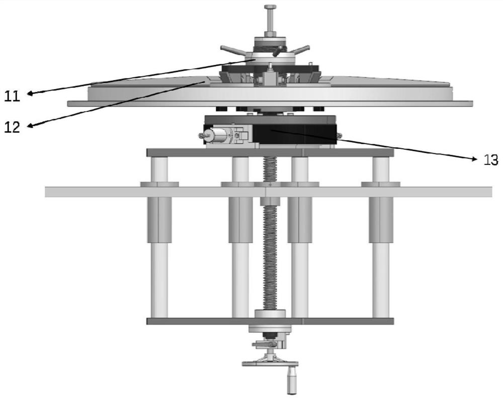
[0026] Such as figure 1 As shown, a liftable steel strip reel loading mechanism of the present invention includes a steel strip tensioning assembly 11, a steel strip upper limit assembly 12 and a steel strip reel lifting assembly 13; the steel strip to be wound is placed on the steel strip carrying turntable 1204, the steel strip reel 1106 is tightened from the inner ring of the steel strip outward by the steel strip tensioning assembly 11, and then the steel strip upper limit assembly 12 is used to limit the axial position of the steel strip reel 1106 to ensure that the steel strip reel 1106 is axially limited during the continuous winding process. The strip output is stable, and the steel strip reel 1106 , the steel strip carrying turntable 1204 , the steel strip tensioning assembly 11 and the steel strip upper limit assembly 12 realize the steel strip height adjustment function thr...

Embodiment 2

[0027] Embodiment 2: the specific structure of steel strip tensioning assembly 11

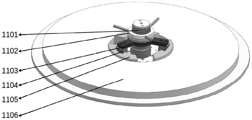
[0028] Such as figure 2 , image 3 As shown, the steel strip reel 1106 to be wound is placed on the steel strip carrying turntable 1204, and the steel strip tensioning push block 1105 passes through the inner diameter of the steel strip reel 1106, and rotates clockwise to lock with the mandrel sleeve 1101. The nut 1102 pushes the inclined pin frame 1103 to move downward, and then the inclined pin 1104 pushes the tensioning push block 1105 to complete the tensioning action of the steel strip reel.

Embodiment 3

[0029] Embodiment 3: the specific structure of the steel band upper limit assembly 12

[0030] Such as Figure 4 , Figure 5 As shown, the tail of the steel strip upper limit plate 1201 in the steel strip upper limit assembly 12 is connected with the rotating shaft seat 1203 through pins, and can realize the action of folding up 90°. The above parts can make the steel strip tighten when the station is folded upward. The components pass through the inner hole of the steel strip reel smoothly, and when the station is folded down, the steel strip reel 1106 can be pressed against the steel strip carrying turntable 1204 through the compression cap 1202, thereby realizing the axial compression limit of the steel strip reel. bit.


PUM


Abstract

The invention belongs to the technical field of mechanical turntable loading, and relates to a liftable steel belt reel loading mechanism. The mechanism comprises a steel belt tensioning assembly (11), a steel belt upper limiting assembly (12) and a steel belt reel lifting assembly (13), so that the functions of tensioning, limiting and winding height adjusting of a steel belt reel are achieved. While a stable bearing function is provided for winding steel strips, the distance between every two adjacent steel strips can be adjusted at the millimeter level, and stable and accurate winding is achieved. A plurality of units are used in cooperation to achieve full-size synchronous winding with a stress high-pressure die, and it is guaranteed that axial prestress of the die is uniform.

Description

technical field [0001] The invention belongs to the technical field of mechanical turntable loading, and in particular relates to a loading mechanism for a pretightening high-pressure mold to be wound with a steel coil. Background technique [0002] The Belta-type double-top hydraulic press is a high-pressure generating device widely used in foreign high-pressure scientific research and production of artificial superhard materials, but it has not been widely used in my country. The fundamental reason is that the core technology (including materials) of high-pressure mold preparation has yet to be resolved. The prestressed high-pressure mold with winding design is an effective means to reduce the material requirements of high-pressure mold and improve its comprehensive performance. [0003] my country is a big producer of superhard materials, and its output accounts for more than 95% of the world's total output. However, there is still a certain gap between high-quality syn...

Claims


Application Information

Patent Timeline
IPC IPC(8): B65H18/02B65H18/10B65H75/24
CPCB65H18/02B65H18/10B65H75/248B65H2701/11332B65H2701/173
Inventor 李洪宇何志朱品文彭刚吴洪伟吕云洲彭寅山王海涛李京
Owner JILIN UNIV
Learn More