Drill bit and drilling equipment
A technology of drill bits and equipment, applied in drilling equipment, drill bits, earth-moving drilling and other directions, can solve problems such as affecting the normal production of oil wells, and achieve the effect of good cleaning effect
- Summary
- Abstract
- Description
- Claims
- Application Information
AI Technical Summary
Problems solved by technology
Method used
Image

Examples
Embodiment 1
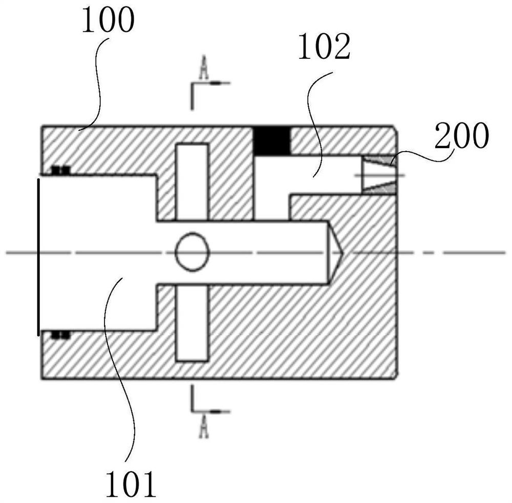
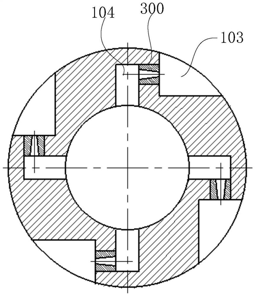
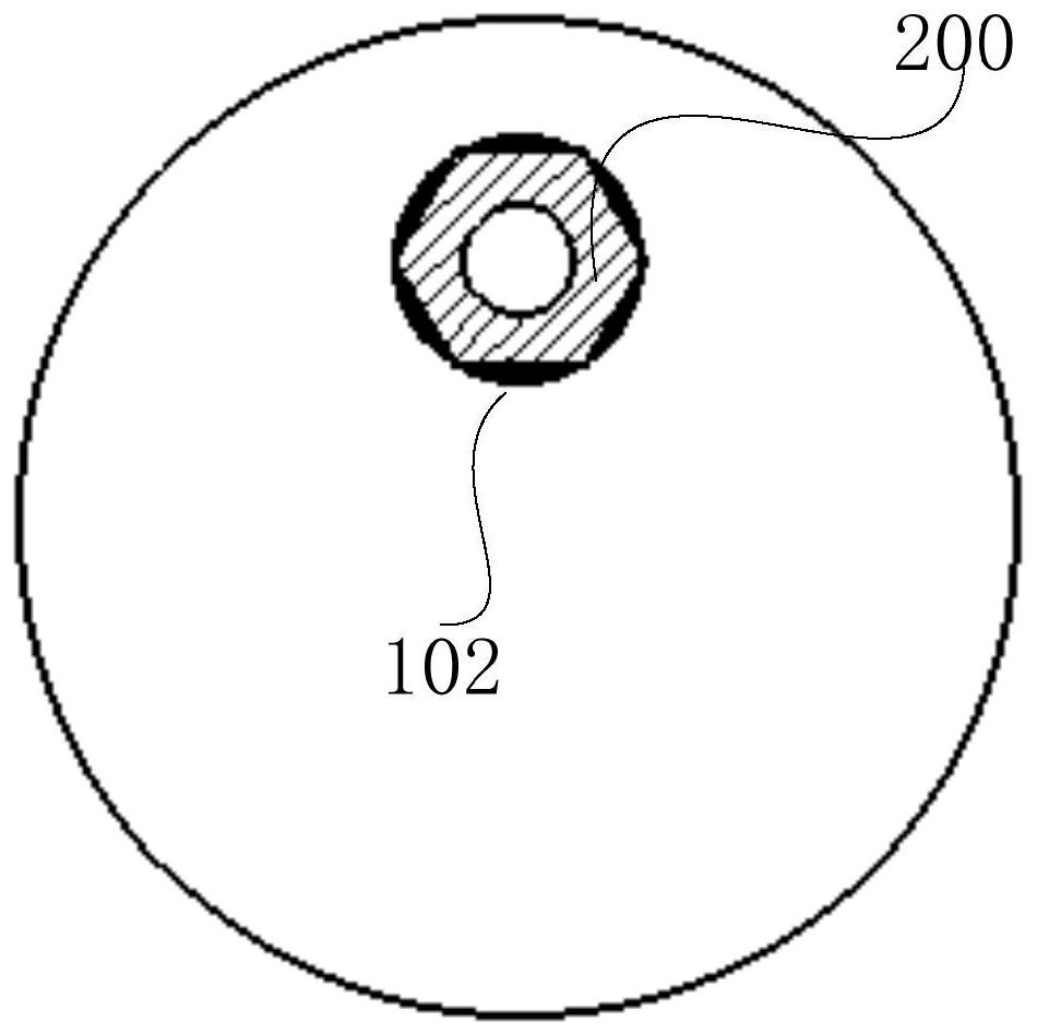
[0054] figure 1For the sectional view of the drill provided in this embodiment, figure 2 for figure 1 Middle A-A sectional view, image 3 A schematic diagram of the first bottom surface structure of the drill provided in this embodiment, Figure 4 A schematic diagram of the second bottom surface structure of the drill provided in this embodiment, combined below Figure 1~4 A specific implementation of the present example will be described in detail.
[0055] This embodiment provides a drill bit, including a drill body 100, a swirl nozzle 200, and a plurality of radial nozzles 300. A main flow channel 101 for fluid flow is formed in the drill body 100, and a plurality of radial nozzles 300 are formed along the Circumferentially arranged on the outer edge of the drill body 100, the radial nozzle 300 communicates with the main channel 101, and multiple radial nozzles 300 spray along multiple tangential directions of the same circle, and the swirl nozzle 200 communicates with...
Embodiment 2
[0072] Figure 5 A cross-sectional view of the installation head of the drilling equipment provided in this embodiment, Figure 6 It is a schematic structural diagram of the sliding sleeve switch of the drilling equipment provided in this embodiment, Figure 7 for Figure 6 Cutaway view of the slide switch shown, Figure 8 The structural representation of the drilling equipment provided for this embodiment, below in conjunction with Figure 5-8 The implementation of this example will be specifically described.
[0073] This embodiment provides a kind of drilling equipment, including installation head 400, oil pipe 700 and any drill bit in the above-mentioned embodiments, the drill bit is detachably connected to the oil pipe 700 through the installation head 400, and the oil pipe 700 is connected to the main flow of the drill bit through the installation head 400 Road 101 connects.
[0074] Specifically, in one example, such as Figure 5 As shown, the mounting head 400 in...
PUM
 Abstract
Description
Claims
Application Information
 - Generate Ideas
- Intellectual Property
- Life Sciences
- Materials
- Tech Scout
- Unparalleled Data Quality
- Higher Quality Content
- 60% Fewer Hallucinations
Browse by: Latest US Patents, China's latest patents, Technical Efficacy Thesaurus, Application Domain, Technology Topic, Popular Technical Reports.
© 2025 PatSnap. All rights reserved.Legal|Privacy policy|Modern Slavery Act Transparency Statement|Sitemap|About US| Contact US: help@patsnap.com