Six-component high-precision micro rolling torque measuring device and measuring method

A torque measurement and high-precision technology, which is applied in the field of aerospace wind tunnel force measurement, can solve the problems of testing and data correction, analysis difficulties, inability to measure six aerodynamic components at the same time, and increase in the number of test vehicles.

Pending Publication Date: 2021-03-19
INST OF HIGH SPEED AERODYNAMICS OF CHINA AERODYNAMICS RES & DEV CENT
View PDF0 Cites 6 Cited by
  • Summary
  • Abstract
  • Description
  • Claims
  • Application Information

AI Technical Summary

Problems solved by technology

[0003] The main disadvantage of adopting this technical solution is that the six aerodynamic components acting on the test model with extremely different loads cannot be measured simultaneously.
One is that the same test state may require repeated tests. Due to the disassembly and assembly of the model, the test state is different and the measurement is very small, which seriously affects the accuracy of the test data; the other is that the number of test trips increases, and the calibration tests carried out by the single-component air-floating balance are all repeated. The cost of the test is very high; the third is that the single-component air-floating balance is installed outside the model, which is very easy to produce a large temperature effect under high-temperature test conditions, which increases the uncertainty of the test data; the fourth is that the test plan is complicated and the test And data correction, analysis is difficult, easy to cause human error

Method used


Image

  • Six-component high-precision micro rolling torque measuring device and measuring method
  • Six-component high-precision micro rolling torque measuring device and measuring method
  • Six-component high-precision micro rolling torque measuring device and measuring method

Examples


Embodiment Construction

[0044]The specification and claims do not use the difference in name as a way to distinguish components, but use the difference in function of components as a criterion for distinguishing. As mentioned throughout the specification and claims, "comprising" is an open term, so it should be interpreted as "including but not limited to". "Approximately" means that within an acceptable error range, those skilled in the art can solve the technical problem within a certain error range and basically achieve the technical effect.

[0045] The orientation terms such as up, down, left, and right in this specification and claims are combined with the drawings for further explanation, making this application easier to understand, and not limiting this application. In different scenarios, up and down, left and right, and inside and outside are all Relatively speaking.

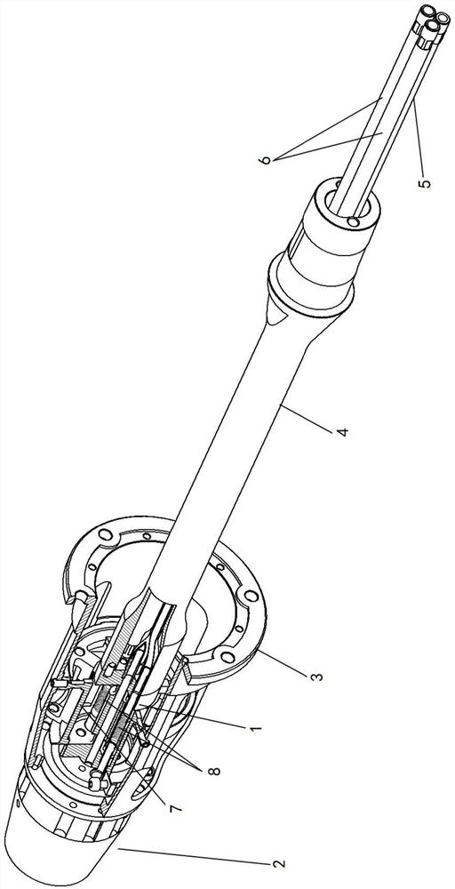
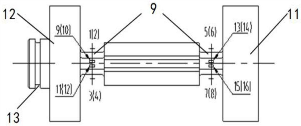
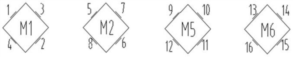
[0046] The present invention will be described in further detail below in conjunction with the accompanying drawings.

...


PUM


Abstract

The invention discloses a six-component high-precision micro rolling moment measuring device, which relates to the technical field of aerospace wind tunnel force measurement tests, can simultaneouslymeasure six aerodynamic components with extremely different loads acting on a test model, and adopts the specific scheme that the six-component high-precision micro rolling moment measuring device comprises a main balance element, a bearing, a model connecting sleeve, a balance supporting rod, an air inlet pipe and an air outlet pipe, wherein the main balance element comprises a supporting rod endand a main balance element model end which are located at two ends respectively, the supporting rod end is connected with the balance supporting rod, the main balance element model end is connected with a stator of the bearing, and a rotor of the bearing is connected with the model connecting sleeve; a rolling resistance element is annularly arranged at the periphery of the main balance element,the rolling resistance element comprises a fixed end and a rolling resistance element model end, and the fixed end is connected with the main balance element model end. The six-component high-precision micro rolling moment measuring device provided by the invention can avoid repeated tests in the same test state, improves test data precision, reduces the test train number, and reduces the test cost.

Description

technical field [0001] The invention relates to the technical field of aerospace wind tunnel force measurement test, more specifically, it relates to a six-component high-precision micro-rolling moment measuring device and a measuring method. Background technique [0002] Aiming at the measurement requirements of the micro-rolling moment of the miniaturized re-entry vehicle test model, the high-speed wind tunnel test is usually carried out by using a single-component air bearing balance based on a gas bearing combined with a large-range six-component small rolling moment test technology. The rolling moment range of the single-component air bearing balance is an order of magnitude smaller than that of the six-component small rolling moment, and the maximum is only 0.02 Nm. Through the reasonable combination and repeated verification of different trips of the single-component air-floating balance and the six-component balance, the moment measurement of the gram-centimeter leve...

Claims


Application Information

Patent Timeline
Patent Type & Authority Applications(China)
IPC IPC(8): G01M9/06G01L5/00G01L5/167
CPCG01L5/00G01L5/167G01M9/06
Inventor 向光伟吕彬彬张璜炜余立汪多炜王树民
Owner INST OF HIGH SPEED AERODYNAMICS OF CHINA AERODYNAMICS RES & DEV CENT
Why Eureka
Try Eureka