
Test equipment for pilotless automobile

A technology for unmanned vehicles and test equipment, applied in the field of unmanned vehicle test equipment, can solve problems such as loose rollers, inaccurate data, irregular vibration, etc., and achieve the goals of avoiding wear and tear, facilitating maintenance, and accelerating replacement speed Effect

Inactive Publication Date: 2021-03-19
张春花
View PDF0 Cites 0 Cited by
  • Summary
  • Abstract
  • Description
  • Claims
  • Application Information

AI Technical Summary

Problems solved by technology

[0004] Aiming at the deficiencies in the prior art, the purpose of the present invention is to provide a test device for unmanned vehicles, to solve the problems in the prior art when using a brake detection platform to detect the brakes of unmanned vehicles During the high-speed movement of the connected rollers, there will be irregular vibrations, which will cause the rollers to become loose, which will cause inaccurate defects in the detected data

Method used


Image

  • Test equipment for pilotless automobile
  • Test equipment for pilotless automobile
  • Test equipment for pilotless automobile

Examples


no. 1 example

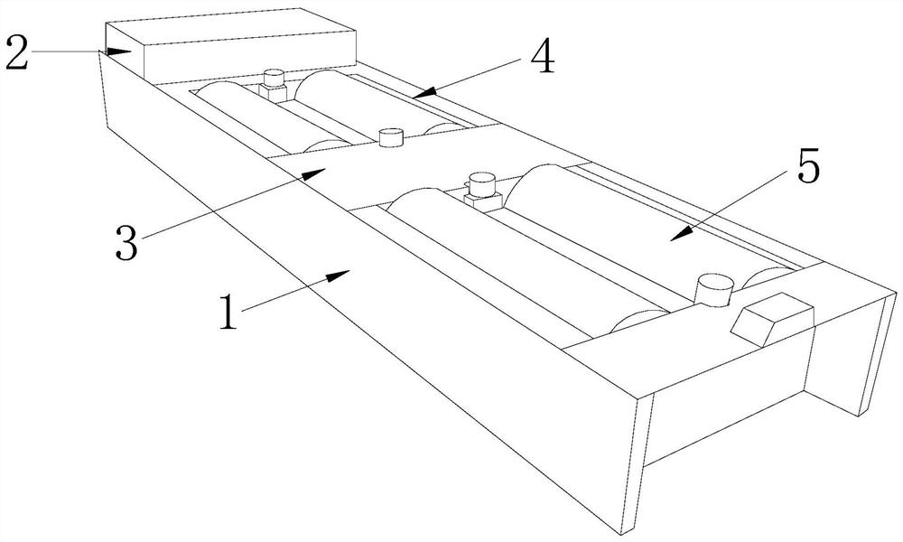
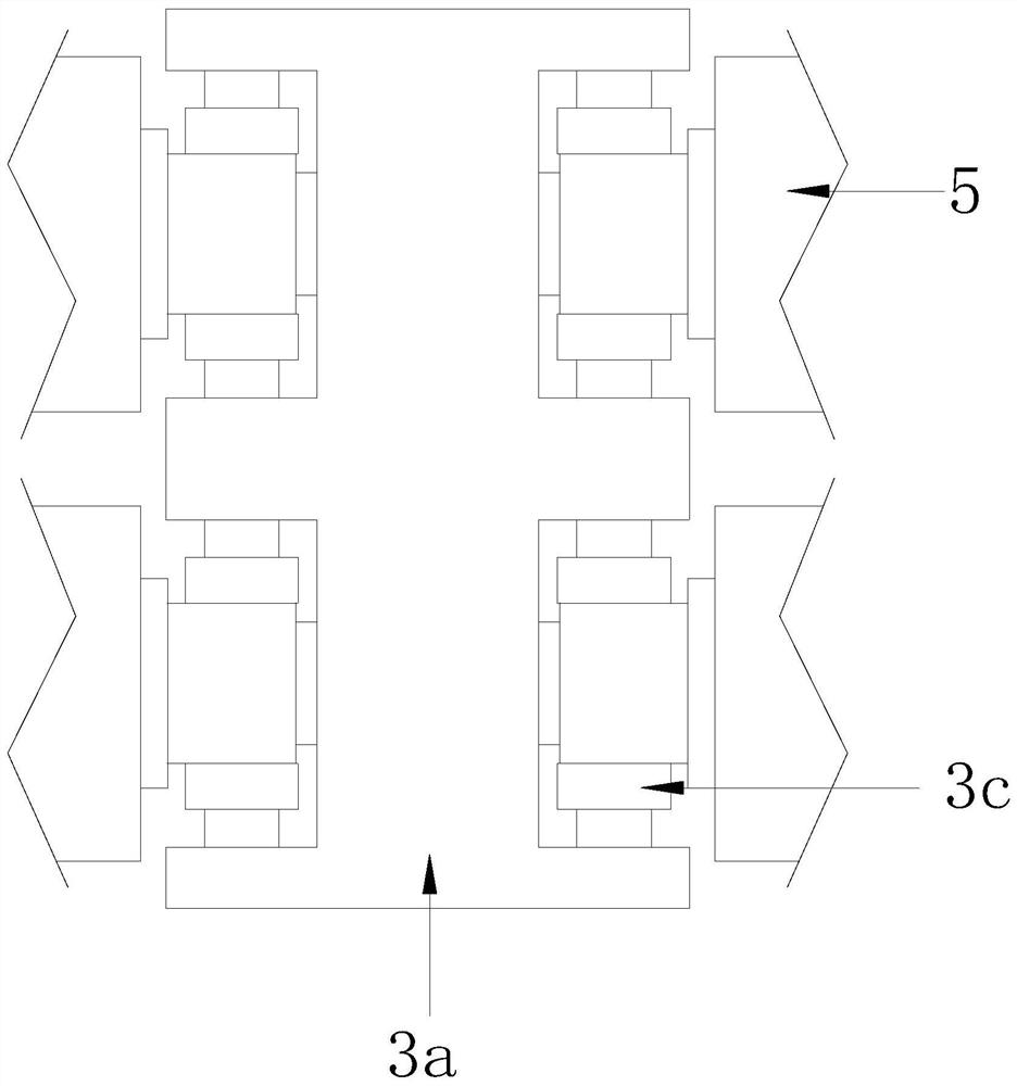
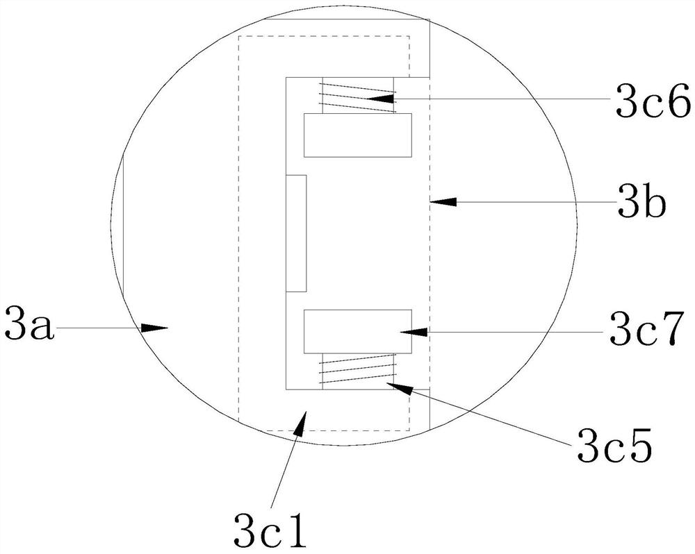
[0030] Such as figure 1 , figure 2 , image 3 , Figure 4 , Figure 5 , Figure 7 Shown, the present invention provides a kind of technical scheme of the test equipment of driverless car:

[0031] Such as Figure 1-Figure 3 As shown, a test equipment for unmanned vehicles, its structure includes a base 1, a power frame 2, a shaft protection device 3, an empty frame 4, and a roller 5, and the power frame 2 is arranged on the left side of the base 1 and connected, The shaft protection device 3 is arranged in the middle of the base 1 and is connected to each other. There are two empty frames 4 which are respectively arranged inside the base 1 with the shaft protection device 3 as the center line. The rollers 5 are in the form of two group and respectively installed inside the empty frame 4, the roller 5 is connected to the contact end of the shaft protection device 3 by fitting and connecting. A total of four openings 3b are installed on the left and right sides of the f...

no. 2 example

[0040] Such as Image 6 Shown, the present invention provides a kind of technical scheme of the test equipment of driverless car:

[0041] Such as Image 6 Shown, a kind of test equipment of unmanned automobile, its structure comprises that said squeeze member 3c4 comprises fixed plate 3c41, pressure push ball 3c42, return spring 3c43, sticking plate 3c44, friction bar 3c45, described fixed plate 3c41 and The conveying plate 3c3 is connected through and connected, and the pressing and pushing ball 3c42 is arranged in the middle of the fixed plate 3c41 and cooperates with each other. It is connected to the front surface of the push ball 3c42, and the friction strips 3c45 are provided with two and are symmetrically installed on the front surface of the sticking plate 3c44 respectively, which is beneficial to cooperate with the cylinder 5 when there is an irregular vibration situation. 5 Do timely suppression of vibration for easy maintenance.

[0042] Such as Image 6 As sho...


PUM


Abstract

The invention discloses test equipment for a pilotless automobile. The test equipment structurally comprises a base, a power frame, a shaft protection device, an empty frame and a roller. The equipment has the beneficial effects that: through the arrangement that the distance between a touch push plate and the surface of the roller is 0.5cm, when the roller vibrates irregularly, the touch push plate is pushed to extrude and cooperate with a bag lantern ring, so that workers can overhaul the bag lantern ring conveniently in time, and meanwhile, when the surface of the touch push plate makes contact with the roller, coarse blocking particles and a rubber layer are arranged on the surface of the touch push plate, the surface of the tail end of the roller is protected and matched so as to prevent collision and other phenomena of the roller in the irregular vibration process from causing unnecessary damage to other parts connected with the roller, an arranged abutting protection mechanism is used for extruding and stabilizing the end face of the roller, and a matching flitch and a friction strip are both of a permanent magnet structure, the roller is prevented from being abraded and collided in the vibration process, so that the replacement speed of the roller is increased, and imprecise brake detection data of a test board for the pilotless automobile is prevented.

Description

technical field [0001] The invention relates to the field of automobile testing equipment, more precisely, a testing equipment for unmanned vehicles. Background technique [0002] Driverless cars are a type of smart cars. With the advancement of technology and unmanned electronic products, a series of safety performance tests are required for the use of driverless cars in daily life. Driving a car mainly relies on the computer system in the car to realize driverless driving. Therefore, while testing it, the testing equipment is also required to have rigorous design and data technology manufacturing. [0003] Among them, when testing the driverless car on the road surface, it includes the motion detection of the driverless car, and when using the braking test bench to detect the braking of the driverless car, the During the high-speed movement of the roller, there will be irregular vibrations, which will cause the roller to become loose, which will make the detected data ina...

Claims


Application Information

Patent Timeline
IPC IPC(8): G01M17/007
CPCG01M17/0074
Inventor 张春花
Owner 张春花
Learn More