

Speed regulation type magnetic coupler with completely separated power source and load and small axial space
A magnetic coupling and complete separation technology, applied in the direction of electric brake/clutch, permanent magnet clutch/brake, electric components, etc., can solve the problems of small axial space, easy damage of speed regulating device, large axial length, etc. Achieve the effect of smooth speed regulation process and simple structure
- Summary
- Abstract
- Description
- Claims
- Application Information
AI Technical Summary
Problems solved by technology
Method used
Image

Examples
Embodiment 1
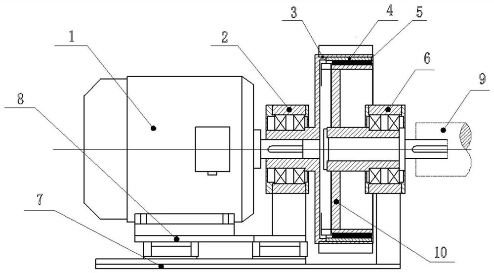
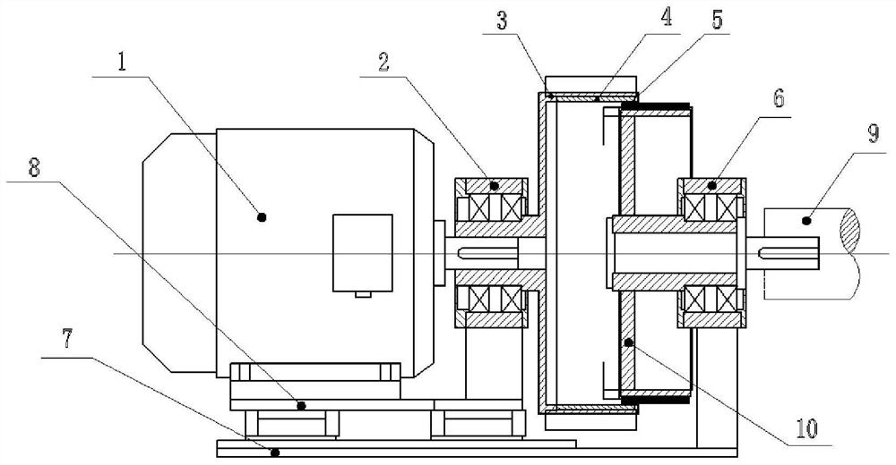
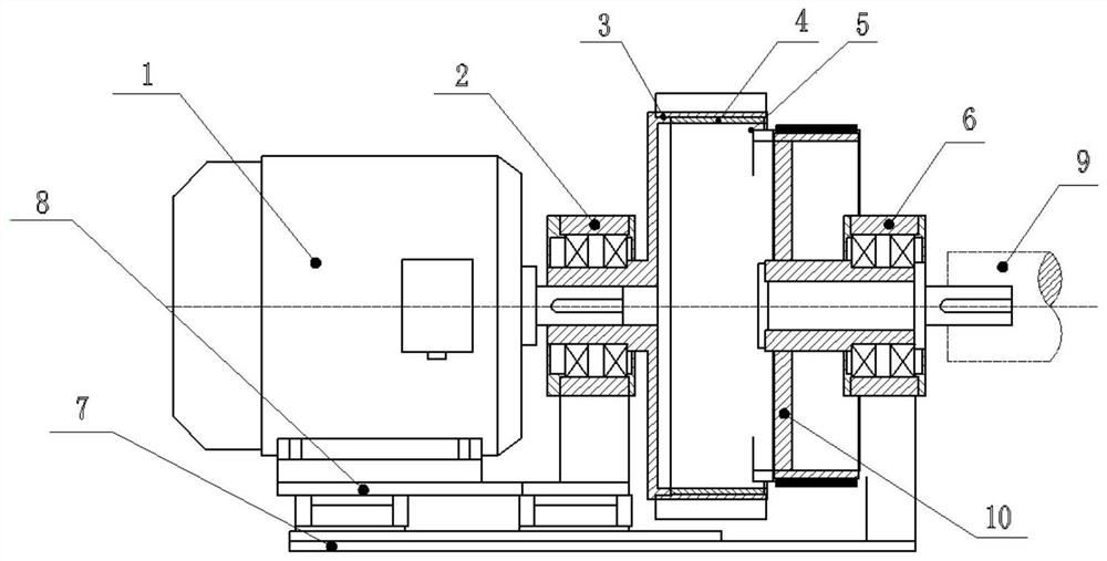
[0028] This embodiment discloses a speed-regulating magnetic coupling with a completely separated power source and load and a small axial space. Its structure is as follows: figure 1 -6, including power source 1, first bearing block 2, second bearing block 6, base plate 7, linear moving platform 8, good conductor end ring 11, first transmission ring 3 and second transmission ring 10.
[0029] The first transmission ring 3 and the second transmission ring 10 are two concentric transmission rings, and the axial length of the first transmission ring 3 is greater than the axial length of the second transmission ring 10 . The material of the first driving ring 3 and the second driving ring 10 is magnetically permeable material. On the wall surface of the largest inner hole of the first drive ring 3, good conductors 4 are evenly distributed in the axial direction, and the good conductor end rings 11 are installed at both ends of the good conductors 4 to short-circuit all the good co...
PUM
 Abstract
Description
Claims
Application Information