Method for manufacturing cylindrical battery and drying apparatus for performing same

A technology for cylindrical batteries and drying equipment, applied in the direction of cylindrical shell batteries/batteries, electrode manufacturing, secondary batteries, etc., can solve the problems of large loss of time, cost and equipment, etc.

Pending Publication Date: 2021-03-19
LG ENERGY SOLUTION LTD
View PDF6 Cites 0 Cited by
  • Summary
  • Abstract
  • Description
  • Claims
  • Application Information

AI Technical Summary

Problems solved by technology

[0009] In the drying process, the electrode plate in the rolled state is placed on a stand under vacuum and high temperature for a long time, and then it is discharged, and in this case, for such a long process, since it is necessary to Storage locations and auxiliary equipment are provided separately, so a lot of time, cost and equipment are lost in mass production

Method used


Image

  • Method for manufacturing cylindrical battery and drying apparatus for performing same
  • Method for manufacturing cylindrical battery and drying apparatus for performing same
  • Method for manufacturing cylindrical battery and drying apparatus for performing same

Examples


example 1

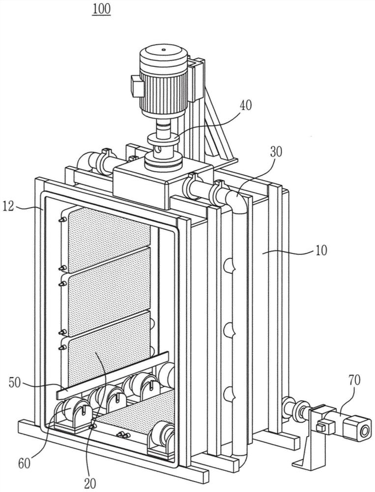
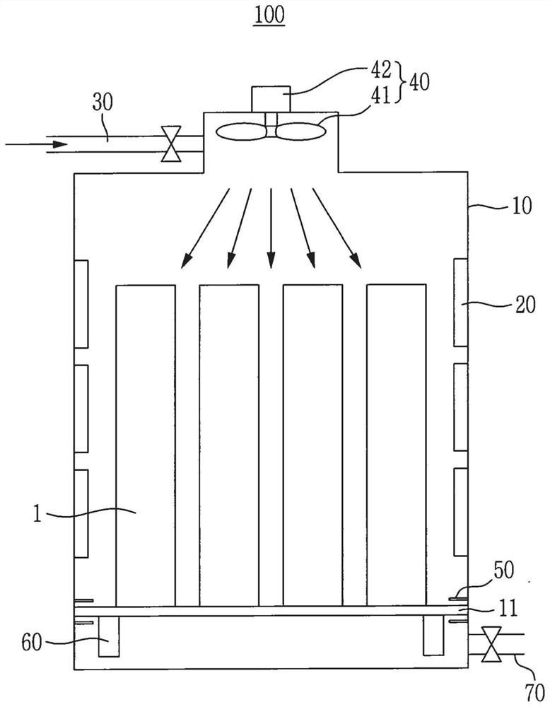
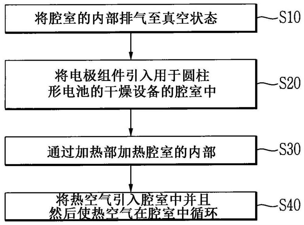
[0060] The positive electrode plate, the negative electrode plate, and the separator interposed between the positive electrode plate and the negative electrode plate were spirally wound to manufacture the electrode assembly 1 having a jelly-roll structure. The initial moisture concentration of the fabricated electrode assembly 1 was 174 ppm in the positive electrode and 337 ppm in the negative electrode.

[0061] Subsequently, after the electrode assembly 1 was accommodated in the chamber 10, drying of the electrode assembly 1 was performed while introducing hot air. In this case, the temperature inside the chamber 10 was raised to 85° C. by the heating portion 20 , and then, the temperature of the supplied hot air was 85° C., and the hot air was supplied for 30 minutes. In this example, measure and Figure 4 shows the change in the amount of moisture in the electrode according to the drying time. Figure 4 (a) shows the change in the amount of moisture in the positive elect...

example 2

[0066] The positive electrode plate, the negative electrode plate, and the separator interposed between the positive electrode plate and the negative electrode plate were spirally wound to manufacture the electrode assembly 1 having a jelly roll structure, and the moisture concentration of the negative electrode was measured. The electrode assembly 1 with an initial negative electrode moisture concentration of 487 ppm was dried under a vacuum of −100 kPa and a temperature of 100° C. for 15 minutes, and then N was introduced when 15 minutes had elapsed. 2 , and the fan 41 was operated at a speed of 30 Hz in a state where the nitrogen gas pressure was 50 kPa, so that additional drying was performed for 15 minutes while the nitrogen gas was circulated. After the drying was completed, the water concentration in the negative electrode was measured to be 257.8 ppm.

example 3

[0068] The positive electrode plate, the negative electrode plate, and the separator interposed between the positive electrode plate and the negative electrode plate were spirally wound to manufacture the electrode assembly 1 having a jelly roll structure, and the moisture concentration of the negative electrode was measured. Electrode assembly 1 with an initial negative electrode moisture concentration of 487 ppm was dried under a vacuum of −100 kPa and a temperature of 100° C. for 27 minutes, and then N was introduced when 27 minutes had elapsed. 2 , and the fan 41 was operated at a speed of 30 Hz in a state where the nitrogen gas pressure was 50 kPa, so that additional drying was performed for 3 minutes while the nitrogen gas was circulated. After the drying was completed, the water concentration in the negative electrode was measured to be 284.9 ppm.


PUM


Abstract

A method for manufacturing a cylindrical battery according to an embodiment of the present invention comprises the steps of: manufacturing an electrode assembly having a jelly-roll structure by preparing a positive electrode plate, a negative electrode plate, and a separator, interposing the separator between the positive electrode plate and the negative electrode plate, and then winding the positive electrode plate, the negative electrode plate, and the separator interposed therebetween; and drying the electrode assembly after the manufacture of the electrode assembly, wherein the step of drying the electrode assembly includes a hot-air circulation drying step.

Description

[0001] Cross References to Related Applications [0002] This application claims priority and benefit from Korean Patent Application No. 10-2018-0142659 filed in the Korean Intellectual Property Office on November 19, 2018, the entire contents of which are incorporated herein by reference. technical field [0003] The invention relates to a method for producing cylindrical batteries and a drying device for carrying out the method. Background technique [0004] In recent years, concerns about rising energy prices and environmental pollution have increased due to the depletion of fossil fuels, and the demand for environmentally friendly alternative energy sources is becoming an indispensable factor in future life. Accordingly, various researches on power generation technologies such as nuclear power, solar power, wind power, and tidal power are underway, and power storage devices for more efficiently using generated energy have also drawn attention. [0005] Also, with the de...

Claims


Application Information

Patent Timeline
Patent Type & Authority Applications(China)
IPC IPC(8): H01M10/04F26B3/02F26B25/16
CPCY02P70/50H01M10/0431H01M10/0409H01M10/0422H01M10/0587F26B21/14F26B3/04F26B21/10F26B5/042F26B21/12Y02E60/10H01M10/049H01M10/0404F26B3/02F26B25/16H01M4/0471
Inventor 禹相珍张宇善姜泰远朴池树朴东赫
Owner LG ENERGY SOLUTION LTD
Why Eureka
Try Eureka