Power transmission tower lifting guide rail mounting structure and power transmission tower

A transmission tower and installation structure technology, which is applied in sports accessories, climbing, etc., can solve the problems of increasing the difficulty of climbing and lifting, reducing the practicality, and large shaking, and achieves the effect of reducing the difficulty of climbing and lifting, improving the practicality, and preventing settlement

Inactive Publication Date: 2021-03-23
胡建刚
View PDF8 Cites 0 Cited by
  • Summary
  • Abstract
  • Description
  • Claims
  • Application Information

AI Technical Summary

Problems solved by technology

[0004] The purpose of the present invention is to provide a kind of installation structure of transmission iron tower lifting guide rail and transmission iron tower, to solve the installation structure of existing transmission iron tower lifting guide rail in the above-mentioned background technology and the transmission iron tower adopts trapezoidal guide rail to prevent falling off when in use, but It shakes a lot during use, which increases the difficulty of climbing and lowering the problem of practicality

Method used


Image

  • Power transmission tower lifting guide rail mounting structure and power transmission tower
  • Power transmission tower lifting guide rail mounting structure and power transmission tower
  • Power transmission tower lifting guide rail mounting structure and power transmission tower

Examples


Embodiment Construction

[0030] The following will clearly and completely describe the technical solutions in the embodiments of the present invention with reference to the accompanying drawings in the embodiments of the present invention. Obviously, the described embodiments are only some, not all, embodiments of the present invention. Based on the embodiments of the present invention, all other embodiments obtained by persons of ordinary skill in the art without making creative efforts belong to the protection scope of the present invention.

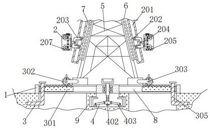
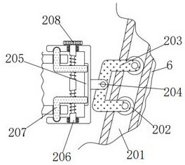
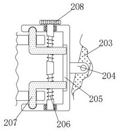
[0031] see Figure 1-6 , the present invention provides a technical solution: an installation structure of a power transmission tower lifting guide rail and a power transmission tower, including a bottom plate 1, a power transmission tower 5 is fixedly connected to the top of the bottom plate 1, and long plates are fixedly connected to the left and right sides of the power transmission tower 5 6. A track mechanism 2 is installed on the outside of the two long ...


PUM


Abstract

The invention discloses a power transmission tower lifting guide rail mounting structure and a power transmission tower. The mounting structure comprises a bottom plate, wherein long plates are fixedly connected to the left side and the right side of the power transmission iron tower correspondingly, rail mechanisms are mounted on the outer sides of the two long plates correspondingly, and each rail mechanism comprises a guide rail, a rolling wheel, a support, a short plate, a square frame, a double-end stud, a bent plate and a handle; and the right side of the guide rail is fixedly connectedwith the left side of a long plate. Through bidirectional fixation of the guide rails in the rail mechanism to the rollers, stable up-down movement of the rollers in the guide rails is achieved, largeshaking during use is avoided, climbing lifting difficulty is reduced, practicability is improved, stability is improved, damage is avoided, danger is reduced, the structure is convenient to use, then grouting is conducted on a wall through a pipeline, wall stability is improved, and the service life of the wall is prolonged; settlement is prevented, the supporting strength is improved, the trouble of later-period reinforcing is omitted, the supporting rods are used for fixing, deviation caused by reinforcing is prevented, the trouble of later-period adjusting is omitted, and use and popularization are convenient.

Description

technical field [0001] The invention relates to the technical field of an installation structure for a lifting guide rail of a power transmission tower and the technical field of a power transmission tower, in particular to an installation structure for a lifting guide rail of a power transmission tower and a power transmission tower. Background technique [0002] The transmission tower is the supporting point of the overhead line. If one circuit is erected on the transmission tower, it is a single-circuit transmission tower, and if two circuits are erected on the transmission tower, it is a double-circuit transmission tower. A single circuit refers to a circuit in which one load has one power supply. ;Double circuit refers to a circuit in which a load has two power supplies. [0003] Although the existing installation structure of the lifting guide rail of the transmission tower and the use of the trapezoidal guide rail to prevent the transmission tower from falling off, it...

Claims


Application Information

Patent Timeline
Patent Type & Authority Applications(China)
IPC IPC(8): A63B27/04
CPCA63B27/04
Inventor 不公告发明人
Owner 胡建刚
Why Eureka
Try Eureka