Grinding tool with cooling structure
A technology for cooling structures and abrasive tools, applied in abrasives, manufacturing tools, bonded grinding wheels, etc., can solve the problems of high cost, low production capacity, complex procedures, etc., to improve the performance of abrasive tools, reduce processing difficulty and processing cost, and improve The effect of the cooling effect
- Summary
- Abstract
- Description
- Claims
- Application Information
AI Technical Summary
Problems solved by technology
Method used
Image

Examples
Embodiment 1
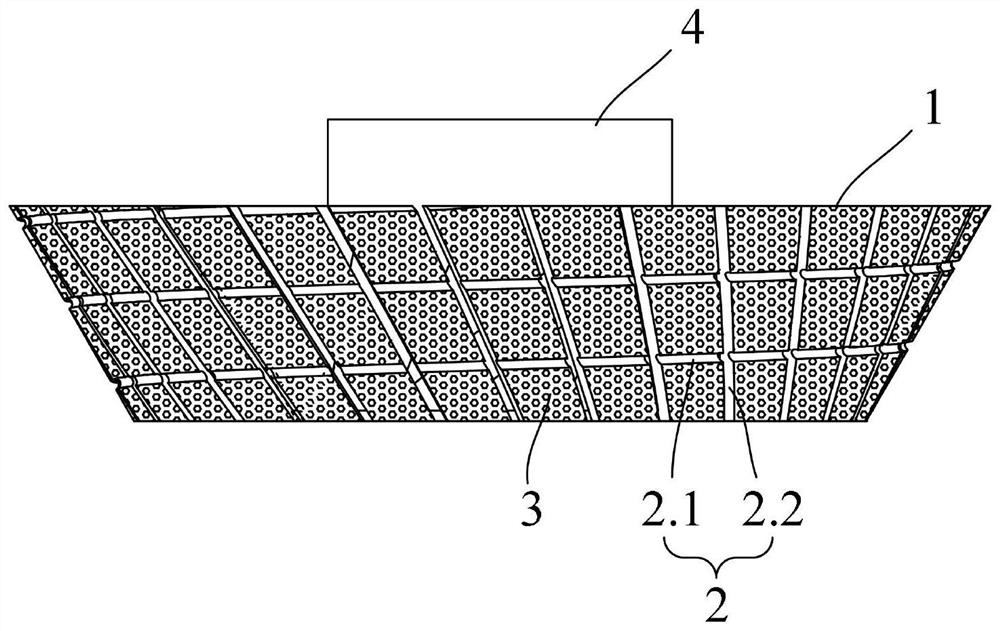
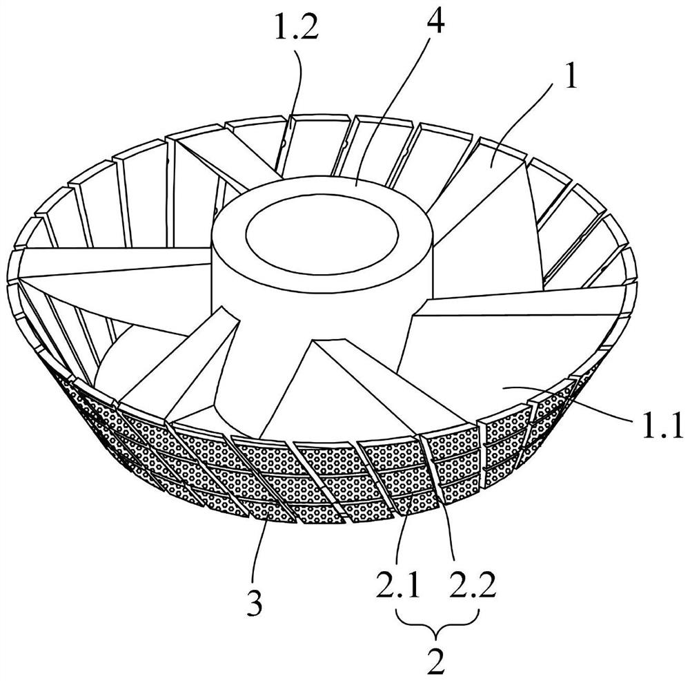
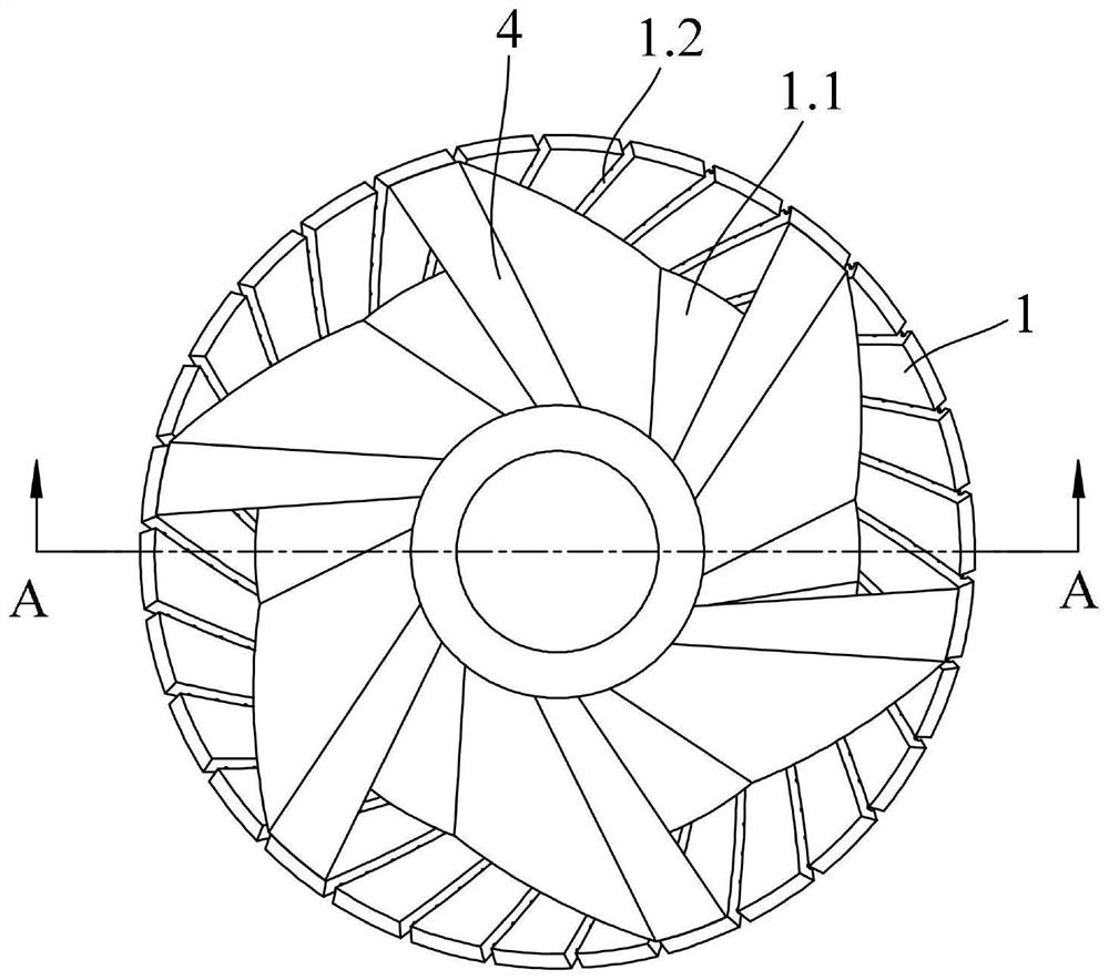
[0052] Such as Figure 1 to Figure 5 As shown, a grinding tool with a cooling structure includes an electroplated grinding disc 1, the grinding end surface of the electroplated grinding disc 1 is provided with a chip removal groove 2; the upper end or lower end of the electroplated grinding disc 1 is provided with A water inlet 1.1, the electroplated grinding piece 1 is provided with a water outlet 1.2 corresponding to its grinding end face, the electroplated grinding piece 1 is provided with a water delivery channel 1.3, and the two ends of the water delivery channel 1.3 are respectively connected to the inlet The water outlet 1.1 is connected to the water outlet 1.2; the chip removal groove 2 is connected to the water outlet 1.2; the grinding end surface of the electroplated grinding disc 1 is provided with a diamond coating 3; the electroplated grinding disc 1, the water outlet Both 1.2 and flutes 2 are made by stamping or laser cutting.
[0053] In the grinding tool of th...
Embodiment 2
[0062] Such as Figure 6 to Figure 10 As shown, a grinding tool with a cooling structure includes an electroplated grinding disc 1, the grinding end surface of the electroplated grinding disc 1 is provided with a chip removal groove 2; the upper end or lower end of the electroplated grinding disc 1 is provided with A water inlet 1.1, the electroplated grinding piece 1 is provided with a water outlet 1.2 corresponding to its grinding end face, the electroplated grinding piece 1 is provided with a water delivery channel 1.3, and the two ends of the water delivery channel 1.3 are respectively connected to the inlet The water outlet 1.1 is connected to the water outlet 1.2; the chip removal groove 2 is connected to the water outlet 1.2; the grinding end surface of the electroplated grinding disc 1 is provided with a diamond coating 3; the electroplated grinding disc 1, the water outlet Both 1.2 and flutes 2 are made by stamping or laser cutting.
[0063] The lower end of the elec...
Embodiment 3
[0070] Such as Figure 11 and Figure 12 As shown, a grinding tool with a cooling structure includes an electroplated grinding disc 1, the grinding end surface of the electroplated grinding disc 1 is provided with a chip removal groove 2; the upper end or lower end of the electroplated grinding disc 1 is provided with A water inlet 1.1, the electroplated grinding piece 1 is provided with a water outlet 1.2 corresponding to its grinding end face, the electroplated grinding piece 1 is provided with a water delivery channel 1.3, and the two ends of the water delivery channel 1.3 are respectively connected to the inlet The water outlet 1.1 is connected to the water outlet 1.2; the chip removal groove 2 is connected to the water outlet 1.2; the grinding end surface of the electroplated grinding disc 1 is provided with a diamond coating 3; the electroplated grinding disc 1, the water outlet Both 1.2 and flutes 2 are made by stamping or laser cutting.
[0071] In the grinding tool ...
PUM
 Abstract
Description
Claims
Application Information
 - R&D Engineer
- R&D Manager
- IP Professional
- Industry Leading Data Capabilities
- Powerful AI technology
- Patent DNA Extraction
Browse by: Latest US Patents, China's latest patents, Technical Efficacy Thesaurus, Application Domain, Technology Topic.
© 2024 PatSnap. All rights reserved.Legal|Privacy policy|Modern Slavery Act Transparency Statement|Sitemap