Pure bending moment yield damper device

A damper and pure bending technology, which is applied in the direction of building components, building structures, earthquake resistance, etc., can solve the problems of local plastic hinges, reduced elongation of welded joints, easy generation of axial force at extended parts, and uneven pressure distribution. Achieve the effects of good energy consumption, high energy absorption and shock absorption performance, and high elongation

Active Publication Date: 2021-03-23
四川极速衍生科技发展有限公司
View PDF20 Cites 0 Cited by
  • Summary
  • Abstract
  • Description
  • Claims
  • Application Information

AI Technical Summary

Problems solved by technology

[0006] In view of the above-mentioned defects of the prior art, the technical problem to be solved by the present invention is that in the prior art, during the use of the bending moment energy dissipator, the core components of the extended energy consumption are welded, etc., and the pressure distribution during use is prone to unevenness, and The extension part is easy to generate axial force, resulting in the reduction of the ductility of the local plastic hinge and welding; the defect of reducing the energy dissipation performance and poor energy dissipation effect

Method used


Image

  • Pure bending moment yield damper device
  • Pure bending moment yield damper device
  • Pure bending moment yield damper device

Examples


Embodiment 1

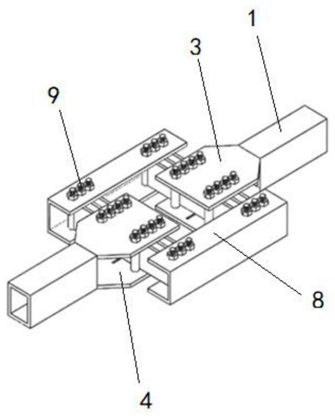
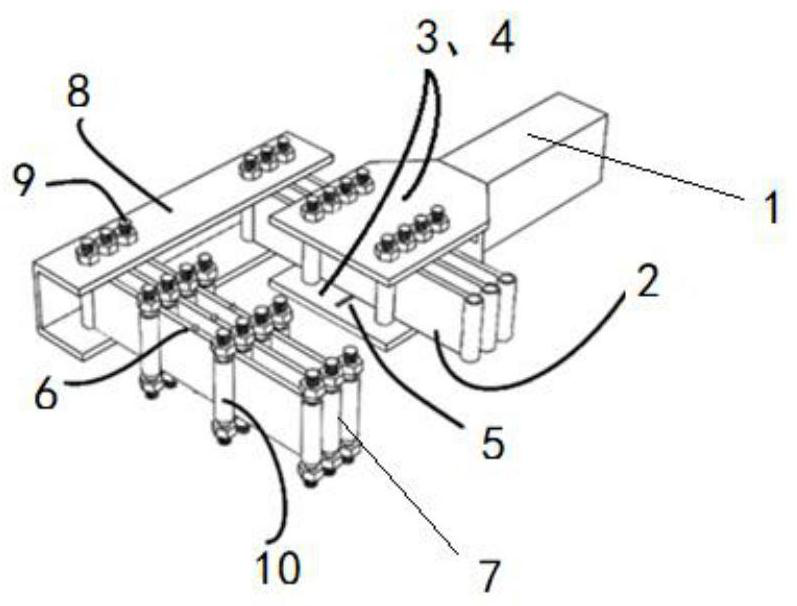
[0051] Such as Figure 1~2 As shown, the pure bending moment yield damper device of the present invention includes a support frame connection port 1, an energy dissipation plate 2, an upper supporting plate 3, a lower supporting plate 4, a guide groove 5, a shear force key 6, and a lateral rolling support 7 , Lateral constraint masonry 8, bearing pin 9, middle rolling bearing 10;

[0052] The connection port 1 of the support frame is two square columns; the support plate includes an upper support plate 3 and a lower support plate 4, and the upper support plate 3 and the lower support plate 4 are two pieces respectively, and the upper support plate 3 is respectively symmetrically welded to the support frame. Above the opening 1, the lower supporting plate 4 is respectively symmetrically welded below the connecting port 1 of the support frame; the supporting plate includes two rows of openings; guide groove 5;

[0053] The rolling support is a hollow cylindrical tube, and the ...

Embodiment 2

[0061] The material of the energy dissipation plate is shape memory alloy; the material of the support frame connection, supporting plate, shear key, rolling bearing and lateral restraint masonry is alloy steel;

[0062] Energy dissipation board 2 is divided into two groups, and the number of each group is 5 pieces

[0063] The ratio of the distance between the energy dissipation panels in each group of energy dissipation panels to the distance between two groups of energy dissipation panels is 1:3;

[0064] The gap distance between the lateral constraint masonry and the upper and lower pallets is 1 / 2 of the pallet width;

[0065] Others are the same as in Example 1, and the pure bending moment yield damper device in Example 2 of the present invention is obtained.

Embodiment 3

[0067] The material of the energy dissipation plate is steel with low yield point; the material of the support frame connection, supporting plate, shear key, rolling bearing and lateral restraint masonry is alloy steel;

[0068] Energy dissipation board 2 is divided into two groups, and the number of each group is 6 pieces

[0069] The ratio of the distance between the energy dissipation panels in each group of energy dissipation panels to the distance between two groups of energy dissipation panels is 1:8;

[0070] The gap distance between the lateral constraint masonry and the upper and lower pallets is 1 / 3 of the pallet width;

[0071] Others are the same as in Example 1, and the pure bending moment yield damper device of Example 3 of the present invention is obtained.

[0072] Take embodiment 1 as an example to introduce the working process of the pure bending moment yield damper device of the present invention:

[0073] Connect the connection port of the support frame t...


PUM


Abstract

The invention discloses a pure bending moment yield damper device. The pure bending moment yield damper device comprises supporting frame connectors, energy dissipation plates, supporting plates, guide grooves, shear keys, rolling supports and lateral constraint masonry. According to the pure bending moment yield damper device, the pressure distribution is uniform, the energy dissipation plates atthe extension part generate pure bending moment, the ductility is high, and it is effectively avoided that when the extension part is used in a welding fixed connection mode, axial force is likely tobe generated, local plastic hinges are caused, and the ductility of the welding position is reduced; the energy consumption performance of the device is improved, the energy absorption and shock absorption performance is high, and the energy consumption effect is good; and the manufacturing cost is low, the operation and later maintenance cost is low, the maintenance and replacement cost after serious earthquake disasters is low, and the applicability is good.

Description

technical field [0001] The invention relates to the technical field of mechanical construction, in particular to a pure bending moment yield damper device. Background technique [0002] In recent years, anti-lateral force systems have become more and more widely used. The lateral force is a horizontal force acting on the building structure for the entire building structure, such as wind force and earthquake force. The anti-lateral force system refers to the system that carries these horizontal forces. Structural damping control systems are widely used in lateral force resistance systems. The existing structural damping control systems mainly fall into three categories: active control systems, passive control systems, and hybrid control systems. The active control system uses multiple sensors, processing systems, and external energy to make the structure reasonably respond to ground excitation; the passive control system refers to the passive response of the system device...

Claims


Application Information

Patent Timeline
Patent Type & Authority Applications(China)
IPC IPC(8): E04B1/98E04B1/36E04H9/02
CPCE04B1/36E04B1/98E04H9/021
Inventor 赛义德·皮拉斯特法哈德·本纳玛法哈桑·齐巴索坎
Owner 四川极速衍生科技发展有限公司
Why Eureka
Try Eureka