
A water-filled motor rotor with high efficiency and corrosion resistance

A motor rotor, corrosion-resistant technology, applied in the direction of electric components, electromechanical devices, electrical components, etc., can solve the problems of damage to the welding points of the rotor guide bar, corrosion of the rotor punching plate, difficult maintenance and replacement, etc., to eliminate electrolysis and prevent cracks and fracture, the effect of a simple structure

Active Publication Date: 2021-07-20
HEFEI HENGDAJIANGHAI PUMP IND CO LTD
View PDF1 Cites 0 Cited by
  • Summary
  • Abstract
  • Description
  • Claims
  • Application Information

AI Technical Summary

Problems solved by technology

[0004] 1. Because the rotor of the original water-filled motor is immersed in water, an electrolytic reaction will occur between the rotor core and the rotor end ring during operation, resulting in corrosion of the part of the rotor plate near the rotor end ring of the motor rotor core.
In severe cases, the rotor guide bar installed in the rotor punch will be exposed, and the welding point between the rotor guide bar and the rotor end ring will be damaged, resulting in extremely harmful faults such as broken bars;
[0005] 2. The existing electronic rotor is fixed by key connection during use, the assembly is difficult, and when the electronic rotor fails, it is difficult to repair and replace;
[0006] 3. The current electronic rotor has poor sealing performance during use

Method used


Image

  • A water-filled motor rotor with high efficiency and corrosion resistance
  • A water-filled motor rotor with high efficiency and corrosion resistance
  • A water-filled motor rotor with high efficiency and corrosion resistance

Examples


Embodiment Construction

[0037] The following will clearly and completely describe the technical solutions in the embodiments of the present invention with reference to the accompanying drawings in the embodiments of the present invention. Obviously, the described embodiments are only some, not all, embodiments of the present invention. Based on the embodiments of the present invention, all other embodiments obtained by persons of ordinary skill in the art without making creative efforts belong to the protection scope of the present invention.

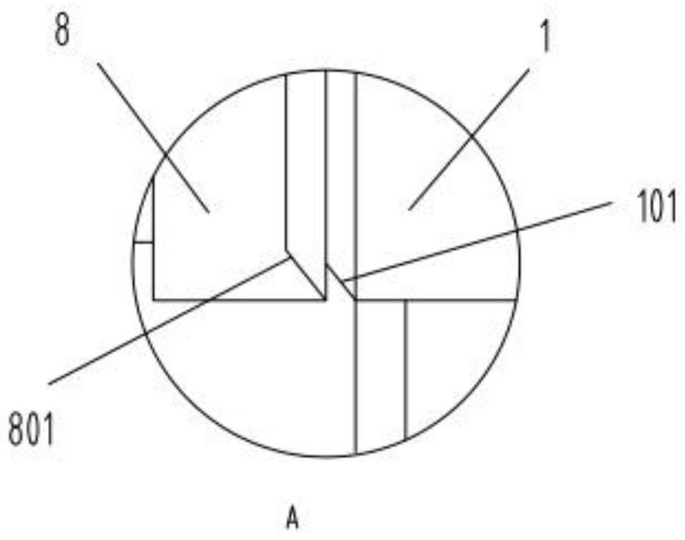
[0038] see Figure 1-7 , in an embodiment of the present invention, a high-efficiency corrosion-resistant water-filled motor rotor includes a rotor guide bar 1, a rotor punch 2, a rotor punch 2 3, a rotor end ring 4, a rotating shaft 6, a fastening block 7 and The locking cover 8, the two ends of the rotor punch 2 are respectively provided with the rotor punch 2 3, and the rotor end ring 4 is arranged on the outer surface of the rotor punch 2 3 at the two ends...


PUM


Abstract

The invention discloses a high-efficiency corrosion-resistant water-filled motor rotor, a high-efficiency corrosion-resistant water-filled motor rotor, including rotor guide bars, rotor punching piece 1, rotor punching piece 2, rotor end rings, a rotating shaft, a tight The solid block and the locking cover, the two ends of the rotor punch one are respectively provided with the rotor punch two, and the rotor end rings are arranged on the outer surface of the rotor punch two at the two ends of the rotor punch one, and the rotor punch A number of rotor guide bars are inserted into the inside of piece 1, and the two ends of the rotor guide bars pass through the rotor punching piece 2 to offset the rotor end ring. The rotor punching piece 1 is sleeved on the rotating shaft through the central through hole, and the rotor punching piece One is fixed and installed on the rotating shaft through the fastening blocks at both ends and the locking cover. The first rotor punching piece is made of silicon steel sheet, and the second rotor punching piece is made of stainless steel sheet. Punching piece 2 is punched from a magnetically conductive stainless steel sheet, thereby eliminating the electrolysis phenomenon between the rotor guide bar and the rotor end ring.

Description

technical field [0001] The invention belongs to the technical field of submersible motors, in particular to a high-efficiency corrosion-resistant water-filled motor rotor. Background technique [0002] The submersible motor is the main component of the submersible pump. The technical performance, structural characteristics, quality, and reliability of the submersible motor largely determine the overall performance of the submersible pump. As a kind of submersible motor, water-filled submersible motor is widely used in industrial and agricultural production, mining, urban construction and other fields. [0003] For example, Patent Application No. 201320263592.7 discloses a rotor that can reduce the water friction loss of a water-filled submersible motor, including the rotor of the submersible motor. The middle part of the rotor is an iron core, and the two ends of the iron core are respectively provided with end rings and balance rings; Between the top surface of the balance...

Claims


Application Information

Patent Timeline
Patent Type & Authority Patents(China)
IPC IPC(8): H02K1/22H02K1/32H02K7/04
CPCH02K1/22H02K1/32H02K7/04
Inventor 朱庆龙梁樑胡薇汪冰金雷魏庆军
Owner HEFEI HENGDAJIANGHAI PUMP IND CO LTD
Learn More