Rotating electrical machine
A technology of rotating electrical machines and conductive components, applied in the direction of electromechanical devices, electrical components, electric components, etc., can solve the problems of difficulty in embedding conductive components, short fitting parts, poor productivity, etc., and achieve assembly and insulation Effect
- Summary
- Abstract
- Description
- Claims
- Application Information
AI Technical Summary
Problems solved by technology
Method used
Image

Examples
Embodiment approach 1
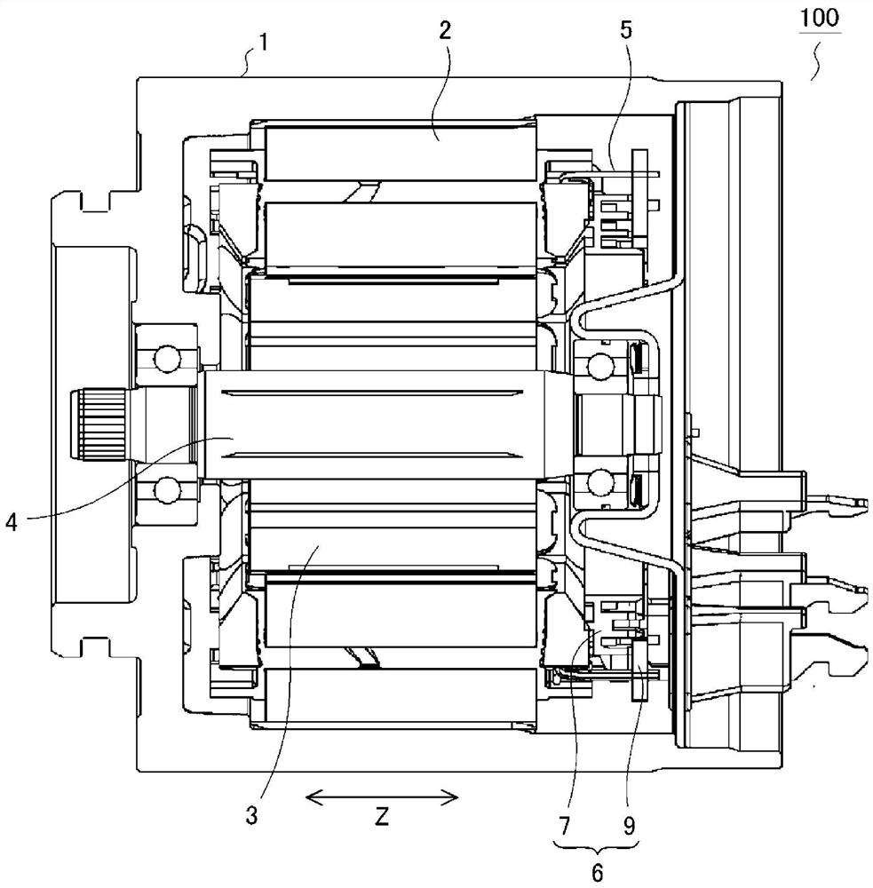
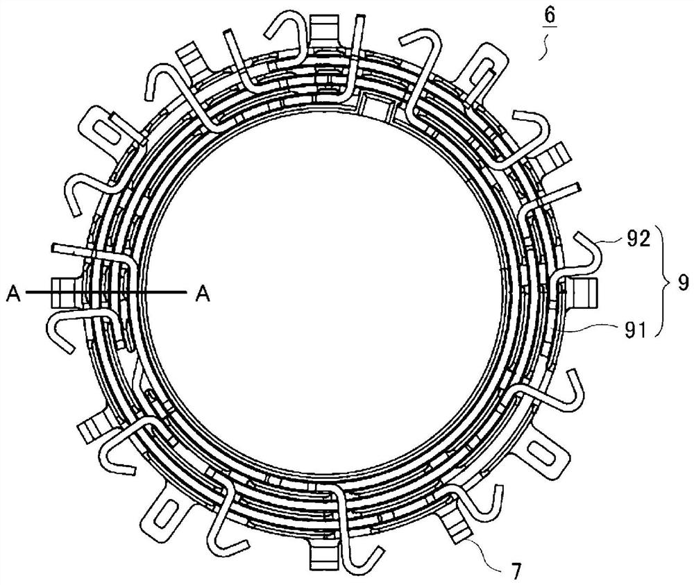
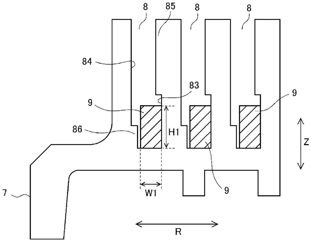
[0028] Hereinafter, the rotary electric machine of the first embodiment will be described based on the drawings. figure 1 It is a cross-sectional view showing the rotary electric machine of the first embodiment, figure 2 It is a top plan view showing a coil connecting body of a rotary electric machine according to the first embodiment, image 3 Yes figure 2 A cross-sectional view of the part represented by A-a. In addition, Figure 4 It is a partial cross-sectional view showing the holder of the coil connectors of the first embodiment. In each figure, for the same, a substantial part is labeled the same symbol. Further, in the figure, the arrow z represents the axial direction of the rotating electric machine, and the arrow R represents the radial direction of the rotary electric machine.
[0029] The rotary electric machine 100 of Embodiment 1 can be used in electric power steering drive motors, etc. figure 1 As shown, the stator 2 is applied in the inner circumference of the...
Embodiment approach 2
[0046] In Embodiment 2, a modification of the holder or terminal of the coil connector will be described. Figure 5 to 7 It is a partial cross-sectional view showing the coil connectors of the second embodiment. Figure 5 to 7 The retainer 7a, 7b, 7b, 7b, 7 have three slots 8 in the heart-shaped, since the cross-sectional shape of the respective grooves 8 is the same, and therefore, a part of the accompanying drawings are omitted. Further, since the overall structure of the rotary electric motor of the second embodiment is the same as the above-described first embodiment, the description thereof will be omitted herein.
[0047] Figure 5 The retaining frame 7a shown has an inclined portion 85c at the extension portion 85 provided in one side wall 83, which is used to enlarge the width size W2 of the groove opening portion 81. Further, another side wall 84 has an inclined portion 84a, which is used to enlarge the width dimension W2 of the groove opening portion 81. According to th...
Embodiment approach 3
[0052] In the third embodiment, the arrangement examples of the holder of the coil connector and the arrangement example of the positioning protrusion will be described. Figure 8 to 10 It is a plan view showing a configuration example of the extension portion and the positioning protrusion portion of the coil connecting body of the third embodiment. In addition, in Figure 9 with Figure 10 In the inner circumferential groove 8, the extension portion 85 and the positioning protrusion 86 are shown, but the other grooves 8 are also the same. Further, since the overall structure of the rotary electric machine of the third embodiment is the same as that of the first embodiment, the description thereof will be omitted herein.
[0053] in Figure 8 In the configuration example shown, the extending portion 85 and the positioning protrusion portion 86 are set through the entire circumference of the groove 8. The holder 7 composed in this manner can reliably suppress floating from the term...
PUM
 Abstract
Description
Claims
Application Information
 - R&D Engineer
- R&D Manager
- IP Professional
- Industry Leading Data Capabilities
- Powerful AI technology
- Patent DNA Extraction
Browse by: Latest US Patents, China's latest patents, Technical Efficacy Thesaurus, Application Domain, Technology Topic.
© 2024 PatSnap. All rights reserved.Legal|Privacy policy|Modern Slavery Act Transparency Statement|Sitemap