Ophthalmology and optometry instrument for objective visual general inspection
A technology of optometry and vision, which is applied in the field of medical devices, can solve problems such as inconvenient carrying and affecting normal detection, and achieve the effects of easy carrying, improved accuracy, and simple operation
- Summary
- Abstract
- Description
- Claims
- Application Information
AI Technical Summary
Problems solved by technology
Method used
Image

Examples
Embodiment Construction
[0028] The implementation mode of the present invention is illustrated by specific specific examples below, and those who are familiar with this technology can easily understand other advantages and effects of the present invention from the contents disclosed in this description. Obviously, the described embodiments are a part of the present invention. , but not all examples. Based on the embodiments of the present invention, all other embodiments obtained by persons of ordinary skill in the art without making creative efforts belong to the protection scope of the present invention.
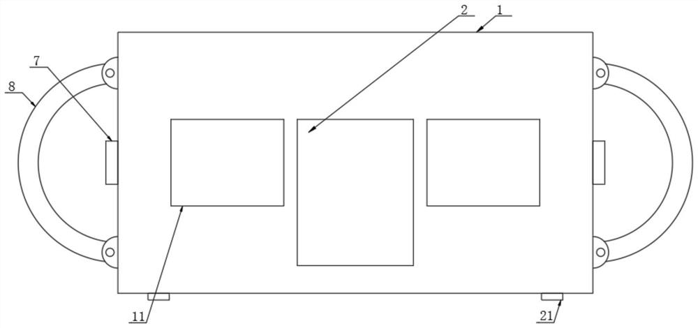
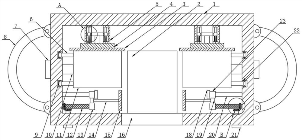
[0029] Refer to the attached figure 1 , 2 , 3 and 6, a kind of optometry instrument that is used for objective visual survey of this embodiment, comprises box body 1, and described box body 1 front and back sides are all provided with observation port 2, and described box body 1 bottom end is opened There are slots 16, and both sides of the box body 1 are provided with binding straps 8, and the...
PUM
 Abstract
Description
Claims
Application Information
 - Generate Ideas
- Intellectual Property
- Life Sciences
- Materials
- Tech Scout
- Unparalleled Data Quality
- Higher Quality Content
- 60% Fewer Hallucinations
Browse by: Latest US Patents, China's latest patents, Technical Efficacy Thesaurus, Application Domain, Technology Topic, Popular Technical Reports.
© 2025 PatSnap. All rights reserved.Legal|Privacy policy|Modern Slavery Act Transparency Statement|Sitemap|About US| Contact US: help@patsnap.com