Positioning-assisted equipment for tumor surgery excision

A technology of surgical resection and positioning assistance, which is applied in the field of medical devices, can solve the problems of inability to resect tumors and achieve surgical effects, and achieve good resection, good surgical effects, and good positioning-assisted operations

Inactive Publication Date: 2021-03-26
焦旭光
View PDF7 Cites 0 Cited by
  • Summary
  • Abstract
  • Description
  • Claims
  • Application Information

AI Technical Summary

Problems solved by technology

[0002] Tumor surgery refers to the process of resecting the tumor while expanding the scope of resection, and removing suspicious tissues and lymph nodes around the tumor in order to achieve the goal of radical cure. In the process of tumor surgical resection, assistance is required. Positioning operation; currently, in the process of tumor surgical resection, it is impossible to better perform positioning-assisted operations, resulting in the inability to better resect the tumor, achieve better surgical results, and fail to better meet people's needs. Use needs, so now there is a need for a positioning aid for tumor surgical resection

Method used


Image

  • Positioning-assisted equipment for tumor surgery excision
  • Positioning-assisted equipment for tumor surgery excision
  • Positioning-assisted equipment for tumor surgery excision

Examples


Embodiment 1

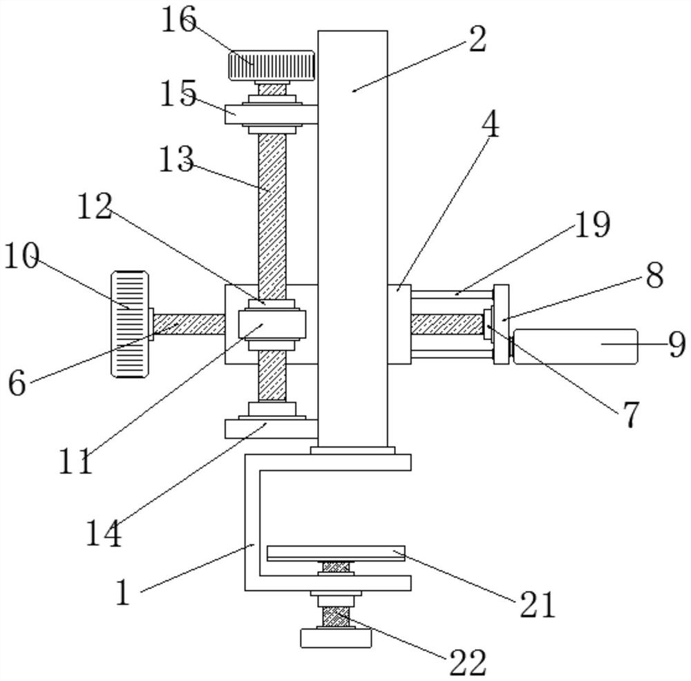
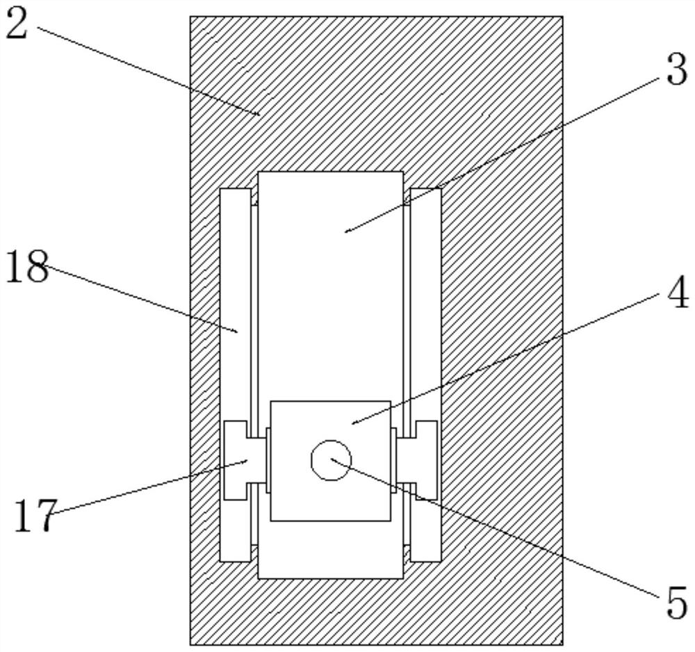
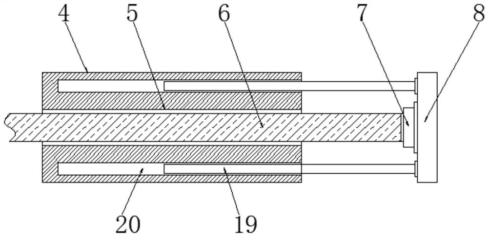
[0019] Embodiment 1: This auxiliary positioning device for tumor surgical resection includes a fixed frame 1, a support plate 2 is installed on the top of the fixed frame 1, and a movable groove 3 is opened inside the support plate 2, and the movable The inside of the groove 3 is equipped with a movable bar 4 that is compatible with the movable groove 3, and the inside of the movable bar 4 is provided with a threaded hole 5, and the inside of the threaded hole 5 is provided with a threaded hole 5 that is compatible with the threaded hole 5. Matching threaded rod one 6, one end of said threaded rod one 6 is equipped with a movable connection shaft 7, and said movable connection shaft 7 is equipped with a connecting block 8 away from the side of said threaded rod one 6, said connection Block 8 is equipped with positioning ring 9 away from the bottom end of the side of the movable connection shaft 7, and a rotating block 10 is installed at the end of the threaded rod-6 away from t...

Embodiment 2

[0020] Embodiment 2: Both sides of the movable bar 4 are equipped with movable clamping blocks 17, and the inner sides of the movable groove 3 are provided with movable clamping grooves 18 that are compatible with the movable clamping blocks 17 ; Through the interaction between the movable block 17 and the movable card slot 18, the movable bar 4 can achieve better stability, so as to facilitate better auxiliary positioning operations, and then facilitate better Meet people's needs.

Embodiment 3

[0021] Embodiment 3: a positioning rod 19 is installed on the side of the connecting block 8 close to the movable bar 4 and above and below the movable connecting shaft 7, and the movable bar 4 is connected with the positioning rod 19 are provided with rod grooves 20 that are compatible with the positioning rods 19; through the interaction between the positioning rods 19 and the rod grooves 20, the positioning ring 9 can achieve better stability. So that it can better meet the needs of people.


PUM


Abstract

The invention provides a position-assisted equipment fixing frame for tumor surgery excision. A supporting plate is arranged at the top of a fixing frame, a movable groove is formed inside the supporting plate, a movable strip matched with the movable groove is arranged in the movable groove, a threaded hole is formed inside the movable strip in a penetrating mode, a threaded rod I matched with the threaded hole is arranged in the threaded hole in a penetrating mode, a movable connecting shaft is arranged at one end of the threaded rod I, a connecting block is arranged on the side edge, away from the threaded rod I, of the movable connecting shaft, a positioning ring is arranged at the bottom end of the side edge, away from the movable connecting shaft, of the connecting block. a rotatingblock I is arranged at the end, away from the movable connecting shaft, of the threaded rod I, a fixing block is arranged on the outer edge of the end, away from the positioning ring, of the movable strip, and a threaded sleeve is arranged in the middle of the fixing block in a penetrating mode.

Description

technical field [0001] The invention relates to a positioning auxiliary device for surgical resection of tumors, and belongs to the technical field of medical instruments. Background technique [0002] Tumor surgery refers to the process of resecting the tumor while expanding the scope of resection, and removing suspicious tissues and lymph nodes around the tumor in order to achieve the goal of radical cure. In the process of tumor surgical resection, assistance is required. Positioning operation; currently, in the process of tumor surgical resection, it is impossible to better perform positioning-assisted operations, resulting in the inability to better resect the tumor, achieve better surgical results, and fail to better meet people's needs. Use demand, so need a kind of positioning auxiliary equipment for surgical resection of tumor now. Contents of the invention [0003] Aiming at the deficiencies in the prior art, the purpose of the present invention is to provide a ...

Claims


Application Information

Patent Timeline
Patent Type & Authority Applications(China)
IPC IPC(8): A61B90/10A61B90/14
CPCA61B90/10A61B90/14
Inventor 焦旭光
Owner 焦旭光
Why Eureka
Try Eureka