Hand massage instrument for children
A hand and children's technology, applied in the direction of equipment for oppressing reflex points, physical therapy, and medical equipment, can solve problems such as children's discomfort, inability to adjust children's massage intensity, and children's massage intensity is not the same, so as to improve the effect. Effect
- Summary
- Abstract
- Description
- Claims
- Application Information
AI Technical Summary
Problems solved by technology
Method used
Image
Examples
Embodiment 1
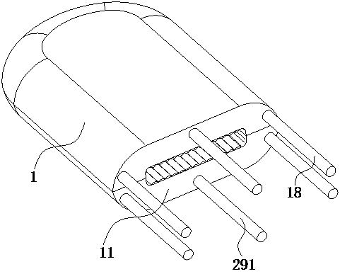
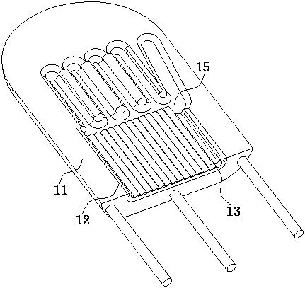
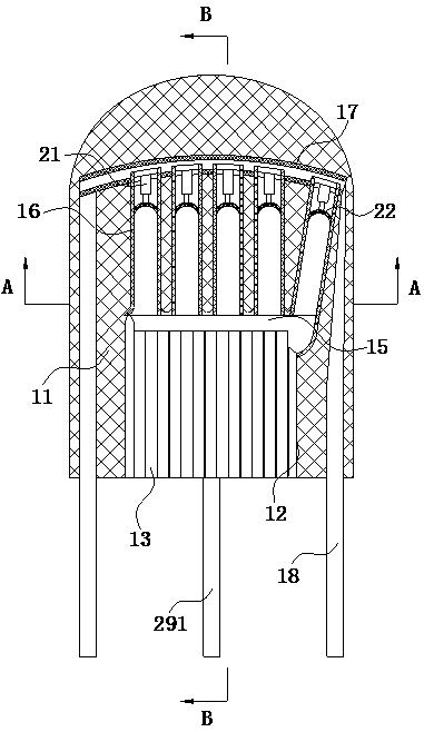
[0038] Example 1, such as Figure 1-Figure 8 As shown, a kind of children's hand massage instrument of the present invention comprises an upper body 1 and a lower body 11; the upper surface of the lower body 11 and the inner wall of the lower body 11 are provided with a palm groove 12; The surface is fixed with uniformly arranged extruded layers 13; under each extruded layer 13, a first through groove 14 is opened in the inner wall of the lower body 11; above the palm groove 12, there is a Finger groove 15; five finger layers 16 are arranged in the finger groove 15; an arc-shaped tube 17 is fixedly connected to the inner wall of the lower body 11 above the finger groove 15, and the finger layers 16 all extend into the arc-shaped tube 17 And it is slidably connected with the arc tube 17; the nozzles on both sides of the arc tube 17 are fixedly connected with the first liquid pipe 18, and the first liquid pipe 18 extends to the outside and communicates with the liquid tank; each...
Embodiment 2
[0045] Example 2, such as Figure 1-Figure 8 As shown, each of the finger layers 16 is a U-shaped design; each of the finger layers 16 is slidingly connected to the side wall of the finger groove 15; each of the finger layers 16 is located on the inner wall of the finger groove 15 There are slots 3 in the middle; each of the slots 3 is rotatably connected with a rotating rod 31; the end faces on both sides of each finger layer 16 are fixedly connected with a second stay cord 32, and the second stay cord 32 Both extend to the outside and connect with the winding rod;
[0046] During work, when there is a difference between the finger and the finger layer 16, the winding rod is rotated at this time, and the second stay cord 32 can be driven to wind during the rotation of the winding rod, and the wound stay cord can pull the finger layer 16 both sides. Stretch and pull the finger layers 16 on both sides into the notch 3. In the process, the upper and lower inner diameters of the...
Embodiment 3
[0047] Example 3, such as Figure 1-Figure 8 As shown, each of the rotating rods 31 is slidably connected to the corresponding slots 3; arc-shaped blocks 33 are fixedly connected to the inner walls of the slots 3 under the edges of both sides of each finger layer 16, and the arc-shaped The block 33 is initially placed under the edges on both sides of the finger layer 16;
[0048]During work, since the arc-shaped block 33 is fixedly connected in the slot 3, when the finger layer 16 both sides are pulled, the arc-shaped block 33 will squeeze the finger layer 16 sliding into the slot 3, and when the finger After the layer 16 is squeezed, the finger layer 16 that slides into the gap 3 can squeeze the rotating rod 31, so that the rotating rod 31 can squeeze the finger layer 16 between the two rotating rods 31, and the finger layer can be tightened in the process. 16, the inner diameters of the left and right sides can be adjusted. In this process, fingers of different thicknesses ...
PUM
 Abstract
Description
Claims
Application Information
 - R&D
- Intellectual Property
- Life Sciences
- Materials
- Tech Scout
- Unparalleled Data Quality
- Higher Quality Content
- 60% Fewer Hallucinations
Browse by: Latest US Patents, China's latest patents, Technical Efficacy Thesaurus, Application Domain, Technology Topic, Popular Technical Reports.
© 2025 PatSnap. All rights reserved.Legal|Privacy policy|Modern Slavery Act Transparency Statement|Sitemap|About US| Contact US: help@patsnap.com


