Solid-liquid extraction and separation reactor

A reactor and liquid immersion technology, applied in the field of solid-liquid leaching and separation reactors, can solve the problems of low removal efficiency, time-consuming and labor-intensive, and inability to check on the machine at any time, and achieve the effect of improving accuracy

Active Publication Date: 2021-03-26
HAINAN UNIVERSITY
View PDF8 Cites 2 Cited by
  • Summary
  • Abstract
  • Description
  • Claims
  • Application Information

AI Technical Summary

Problems solved by technology

[0003] Conventional methods are time-consuming and labor-intensive when there are a large number of experimental samples and the capacity of the centrifuge is limited
Due to the speed limit of the centrifuge, the supernatant after centrifugation of some samples cannot be tested on the machine at any time, and according to the requirements of some experimental instruments, it needs to be filtered through a filter membrane with a certain pore size, which will easily lead to both the front and back sides of the filter membrane. The supernatant on the surface and the side that is in direct contact with the sample hang residues, the removal efficiency is very low, and the disassembly process is a waste of time. When performing experiments on various samples in sequence, the detection efficiency is affected, and the existing equipment uses multiple The separation equipment is used alternately and the corresponding cleaning work is carried out, and the leaching work of another sample cannot be carried out at the same time during the cleaning process of a single separation equipment.

Method used


Image

  • Solid-liquid extraction and separation reactor
  • Solid-liquid extraction and separation reactor
  • Solid-liquid extraction and separation reactor

Examples


Embodiment Construction

[0023] In order to better understand the technical content of the present invention, specific embodiments are provided below, and the present invention is further described in conjunction with the accompanying drawings.

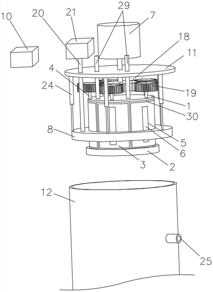
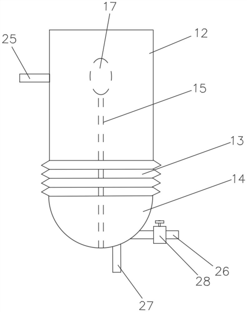
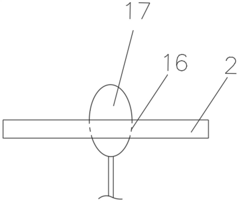
[0024] see Figure 1 to Figure 6 , a solid-liquid leaching separation reactor of the present invention, comprising a top plate 1, a bottom plate 2 and a plurality of arc-shaped plates 3, the arc-shaped plates 3 are fixedly connected with a fixed shaft 4, and the arc-shaped plates 3 are provided with A hole 5, a filter membrane 6 is arranged in the hole 5, the top end of the fixed shaft 4 passes through the top plate 1, the bottom end of the fixed shaft 4 is inserted into the bottom plate 2 and rotates relative thereto, The outside of the top plate 1 is provided with a holding mechanism for replacing the tested sample, a motor 7 is arranged above the holding mechanism, the output end of the motor 7 passes through the holding mechanism, and the The output end ...


PUM


Abstract

The invention discloses a solid-liquid extraction and separation reactor which comprises a top plate, a bottom plate and a plurality of arc-shaped plates; fixed shafts are fixedly connected to the arc-shaped plates, hole grooves are formed in the arc-shaped plates, filter membranes are arranged in the hole grooves, and the top ends of the fixed shafts penetrate through the top plate and the bottomends of the fixed shafts to be inserted into the bottom plate and rotate relative to the bottom plate; a containing mechanism for replacing a tested sample is arranged outside the top plate, a motoris arranged above the containing mechanism, the output end of the motor penetrates through the containing mechanism, the output end of the motor is provided with a transmission mechanism used for rotating the fixed shafts, the transmission mechanism is located in the containing mechanism, and the transmission mechanism is connected with the fixed shafts; and the containing mechanism is provided with a telescopic mechanism, the bottom of the telescopic mechanism is provided with a scraping plate with a circular-ring-shaped cross section, the surface of the scraping plate is provided with a plurality of air bags which are uniformly distributed. The reactor also comprises an air conveying mechanism used for conveying air to the air bags, and a variety of samples can be rapidly detected one byone. And while the cleaning work is carried out, liquid immersion is carried out on another sample and sample components are extracted.

Description

technical field [0001] The invention relates to experimental auxiliary equipment, in particular to a solid-liquid extraction separation reactor. Background technique [0002] When studying the physical and chemical properties of some samples (such as plants, soil), it is necessary to grind the sample fully, weigh a certain weight of the sample and add it to the centrifuge tube, add various extraction reagents as required, and then dissolve the components in the sample to extract In the reagent, the supernatant and the residue are obtained after centrifugation, and the purpose is achieved after separation. [0003] Conventional methods are time-consuming and labor-intensive when there are a large number of experimental samples and the capacity of the centrifuge is limited. Due to the speed limit of the centrifuge, the supernatant after centrifugation of some samples cannot be tested on the machine at any time, and according to the requirements of some experimental instrument...

Claims


Application Information

Patent Timeline
Patent Type & Authority Applications(China)
IPC IPC(8): B01D11/02G01N1/40B08B1/00
CPCB01D11/02B08B1/005G01N1/4055G01N1/4077G01N2001/4061G01N2001/4088
Inventor 吴治澎赵庆杰吴蔚东
Owner HAINAN UNIVERSITY
Why Eureka
Try Eureka