Automatic cable fireproof coating spraying equipment with concentration adjusting mechanism
A fire retardant coating and automatic spraying technology, which is applied in the manufacture of cables/conductors, insulation of conductors/cables, circuits, etc., can solve the problems of high labor cost and low degree of automation, and achieve the effect of saving raw liquid
- Summary
- Abstract
- Description
- Claims
- Application Information
AI Technical Summary
Problems solved by technology
Method used
Image
Examples
specific Embodiment approach 1
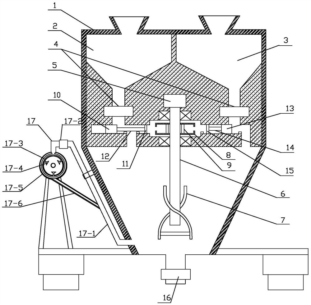
[0019] Specific implementation mode one: as figure 1 As shown, the spraying equipment described in this embodiment includes a stirring tank 1, a stock solution storage tank 2, a diluent storage tank 3, two solenoid valves 4, an automatic concentration adjustment mechanism, a stirring mechanism and a spraying device,
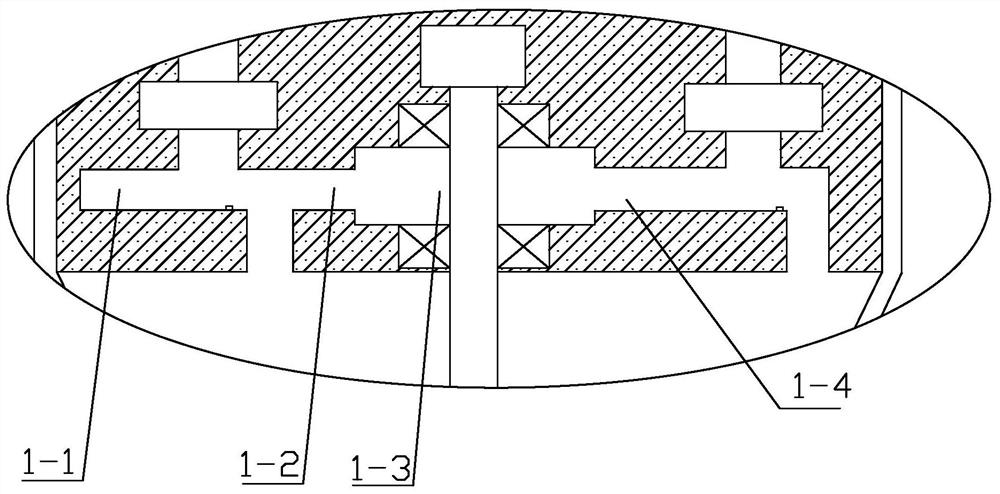
[0020] The mixing box 1 is divided into upper and lower parts, the upper part is a solid body, the lower part is a cavity and used as a mixing chamber, and the upper part of the mixing box 1 is horizontally opened with a plurality of sequentially connected cavities , respectively the first cavity 1-1, the second cavity 1-2, the third cavity 1-3 and the fourth cavity 1-4, the third cavity 1-3 is a cylindrical cavity ,
[0021] The stock solution storage box 2 and the dilution solution storage box 3 are embedded side by side in the upper half of the stirring box 1, and the feed inlets of the stock solution storage box 2 and the dilution solution storage box 3 are ...
specific Embodiment approach 2
[0028] Specific embodiment 2: This embodiment is a further description of the stirring box described in Specific Embodiment 1. In this embodiment, the bottom of the stirring tank 1 is provided with a discharge port, and a discharge port is provided on the discharge port. Solenoid valve 16: After finishing the spraying work, due to the short deterioration time of the fireproof coating, and the spraying needs to be carried out once every 12 hours, the redundant fireproof coating can be discharged through the discharge port and the discharge solenoid valve by opening the discharge solenoid valve.
specific Embodiment approach 3
[0029]Specific embodiment three: This embodiment is a further description of the spraying device described in specific embodiment two. In this embodiment, the spraying device also includes a residual material recovery tank 17-5 and a residual material recovery pipe 17-6 , the residual material recovery tank 17-5 is a circular tank body, the nozzle 17-4 is in the tank of the residual material recovery tank 17-5, and the nozzle of the nozzle 17-4 is facing the residual material recovery tank 17-5 at the center of the circle, where the cable is set at the center of the surplus material recovery tank 17-5, and the nozzle 17-4 sprays it with paint, and one end of the surplus material recovery pipe 17-6 is connected to the surplus material recovery tank The tank bottom of 17-5 communicates, and the other end of surplus material recovery pipe 17-6 communicates with feeding pipe 17-1;
[0030] Utilize the remaining material recovery tank 17-5 to recover the remaining paint received in...
PUM
 Abstract
Description
Claims
Application Information
 - R&D
- Intellectual Property
- Life Sciences
- Materials
- Tech Scout
- Unparalleled Data Quality
- Higher Quality Content
- 60% Fewer Hallucinations
Browse by: Latest US Patents, China's latest patents, Technical Efficacy Thesaurus, Application Domain, Technology Topic, Popular Technical Reports.
© 2025 PatSnap. All rights reserved.Legal|Privacy policy|Modern Slavery Act Transparency Statement|Sitemap|About US| Contact US: help@patsnap.com


