Casting equipment and casting method for light alloy motor shell

A technology for motor housings and casting equipment, which is applied in casting equipment, metal processing equipment, equipment for handling molds, etc., and can solve the problems of not being tight enough to fix molds, affecting casting effects, and reducing practicability, etc.

Inactive Publication Date: 2021-03-26
许彩山
View PDF10 Cites 1 Cited by
  • Summary
  • Abstract
  • Description
  • Claims
  • Application Information

AI Technical Summary

Problems solved by technology

[0004] The purpose of the present invention is to provide a casting equipment for light alloy motor shells, to solve the problem that the existing device proposed in the backgr

Method used


Image

  • Casting equipment and casting method for light alloy motor shell
  • Casting equipment and casting method for light alloy motor shell
  • Casting equipment and casting method for light alloy motor shell

Examples


Embodiment 1

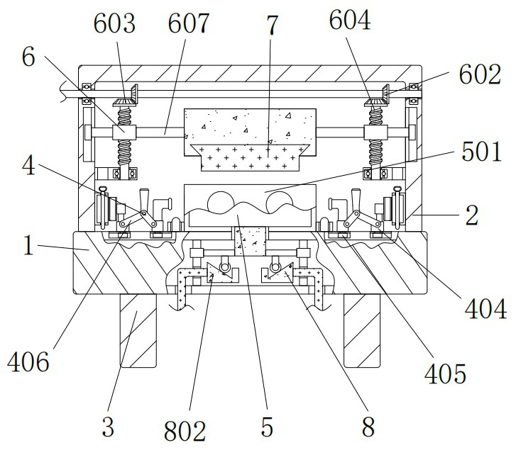
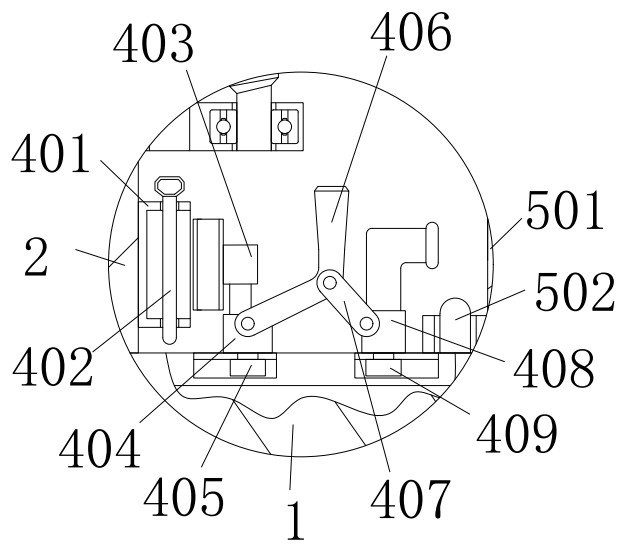
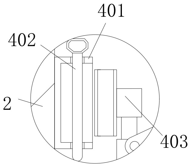
[0034] A casting equipment for light alloy motor casings, comprising a first casing 1, a second casing 2 and a strut 3, the top of the first casing 1 is communicated with a second casing 2, and the The left and right sides of the bottom are fixed with pillars 3. There are four pillars 3 distributed in parallel at the bottom of the first shell 1. The top left and right sides of the first shell 1 are provided with fixing devices 4. The fixing devices 4 include squares. Shell 401, plug 402, vertical cylinder 403, first block 404, first slider 405, curved plate 406, inclined plate 407, second block 408 and second slider 409, the left side of the square shell 401 and the second shell The left side of the inner wall of the body 2 is fixedly connected, the through holes on the upper and lower sides of the square shell 401 are gap-fitted with a plug pin 402, the right side of the plug pin 402 is provided with a vertical cylinder 403, and the plug pin 402 can be inserted in the through ...

Embodiment 2

[0036] As an optional case, see figure 1 , 5And 6, used for light alloy motor shell casting equipment, the first shell 1 is provided with a demoulding device 8 inside, and the demoulding device 8 includes a bent rod 801, a trapezoidal block 802, a thin rod 803, a sliding sleeve 804, a sliding The rod 805 and the thick plate 806, the left side of the outer wall of the bent rod 801 is in clearance fit with the bottom left groove of the first shell 1, the bent rod 801 can move in the bottom left groove of the first shell 1, the bent rod A trapezoidal block 802 is fixed on the upper right side of the 801. A thin rod 803 is attached to the top of the trapezoidal block 802. A sliding sleeve 804 is fixed on the top of the thin rod 803. The upper and lower ends of the rod 805 are fixedly connected to the upper and lower sides of the inner wall of the first housing 1 respectively, and the lower through hole of the outer wall of the sliding rod 805 is in clearance fit with the outer wa...

Embodiment 3

[0039] As an optional case, see figure 1 and 4 , used for light alloy motor housing casting equipment, the inside of the second housing 2 is provided with an auxiliary device 6, the auxiliary device 6 includes a long rod 601, a first gear 602, a second gear 603, a screw 604, a sleeve 605, The horizontal plate 606 and the wide plate 607, the left side of the outer wall of the long rod 601 is rotatably connected to the upper left side of the second housing 2 through a bearing, the left side of the outer wall of the long rod 601 is fixed with a first gear 602, the first gear 602 The bottom is meshed with a second gear 603, the bottom of the second gear 603 is fixed with a screw 604, the outer wall of the screw 604 is threadedly connected with a sleeve 605, and the left side of the outer wall of the sleeve 605 is concave with the left side of the inner wall of the second housing 2. The grooves are slidably connected, and the left side of the outer wall of the sleeve 605 can move ...


PUM


Abstract

The invention discloses a casting equipment for a light alloy motor shell. The casting equipment comprises a first shell, a second shell and a supporting column, wherein fixing devices are arranged onthe left side and the right side of the top of the first shell correspondingly, the outer wall of a first sliding block is slidably connected to a groove in the left side of the top of the first shell in a clamped mode, the front face of a first square block is rotatably connected to a bent plate through a pin shaft, the right side of the front face of the bent plate is rotationally connected toan inclined plate through the pin shaft, the right side of the inclined plate is rotationally connected to the front face of a second square block through the pin shaft, a second sliding block is fixedly connected to the bottom of the second square block, and the outer wall of the second sliding block is slidably connected to a groove in the left side of the top of the first shell in a clamped mode. According to the casting equipment and casting method, through cooperation of the square shell, a plug pin and a vertical cylinder, a lower die can be fixed by pulling a bent plate, the problem that when an existing device works, die fixing is not tight enough is solved, movement is prevented from occurring in a using process, the casting effect is prevented from being affected, and the practicability is improved.

Description

technical field [0001] The invention relates to the technical field of casting equipment for light alloy motor casings, in particular to a casting equipment for light alloy motor casings. Background technique [0002] Casting is a metal thermal processing technology that human beings mastered relatively early, with a history of about 6,000 years. China has entered the heyday of bronze castings between about 1700 BC and 1000 BC, and the craftsmanship has reached a very high level. Casting is a method of casting liquid metal into a casting cavity suitable for the shape of the part, and after cooling and solidifying it, a method of obtaining parts or blanks. Casting is also often used when making light alloy motor casings. [0003] However, the existing device does not fix the mold tightly enough during operation, which leads to movement during use, affects the casting effect, and reduces the practicability, and the existing device is troublesome to demold during operation, re...

Claims


Application Information

Patent Timeline
IPC IPC(8): B22D33/04B22D29/08
CPCB22D29/08B22D33/04
Inventor 许彩山
Owner 许彩山
Why Eureka
Try Eureka