Sand blasting machine for glass

A sandblasting machine and glass technology, applied in the direction of abrasive jetting machine tools, used abrasive processing devices, abrasives, etc., can solve problems such as unstable placement and glass bottom scraping

Inactive Publication Date: 2021-03-26
陈福育
View PDF0 Cites 0 Cited by
  • Summary
  • Abstract
  • Description
  • Claims
  • Application Information

AI Technical Summary

Problems solved by technology

[0004] Aiming at the deficiencies in the prior art, the object of the present invention is to provide a glass sandblasting machine to solve the prior art problem of sandblasting the glass surface. Since the sand and dust on the surface of the conveying plate cannot be completely removed, it will still cause There is a small amount of sand and dust and large grains of sand and stones left, which leads to the defects that the bottom of the glass is in contact with the sand and stones when the glass is placed for the second time, and the placement is unstable and the bottom of the glass is scratched during the transportation process.

Method used


Image

  • Sand blasting machine for glass
  • Sand blasting machine for glass
  • Sand blasting machine for glass

Examples


no. 1 example

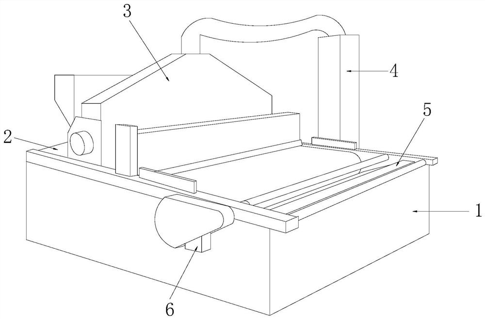
[0030] Such as Figure 1-Figure 5 As shown, the present invention provides a kind of technical scheme of glass blasting machine:

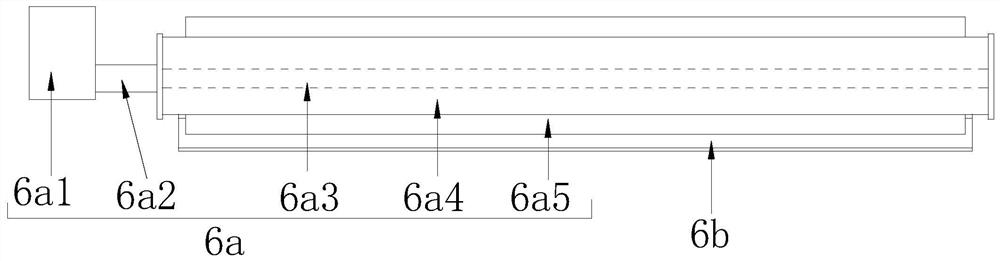
[0031] Such as Figure 1-Figure 3 As shown, a glass sandblasting machine, its structure includes equipment main body 1, conveyor belt 2, sandblasting box 3, dust remover 4, sand return box 5, auxiliary dust removal device 6, said conveyor belt 2 is installed on equipment main body 1 On the upper surface, the sandblasting box 3 is located on the left side of the upper surface of the equipment main body 1, and is located above the conveyor belt 2, the dust collector 4 is matched with the sandblasting box 3, and the sand return box 5 is installed on the equipment main body 1 Inside on the right side, and located on the lower surface of the conveyor belt 2, the auxiliary dust removal device 6 is located at the lower part of the right end of the conveyor belt 2. The auxiliary dust removal device 6 includes a noodle belt cleaning mechanism 6a and an aux...

no. 2 example

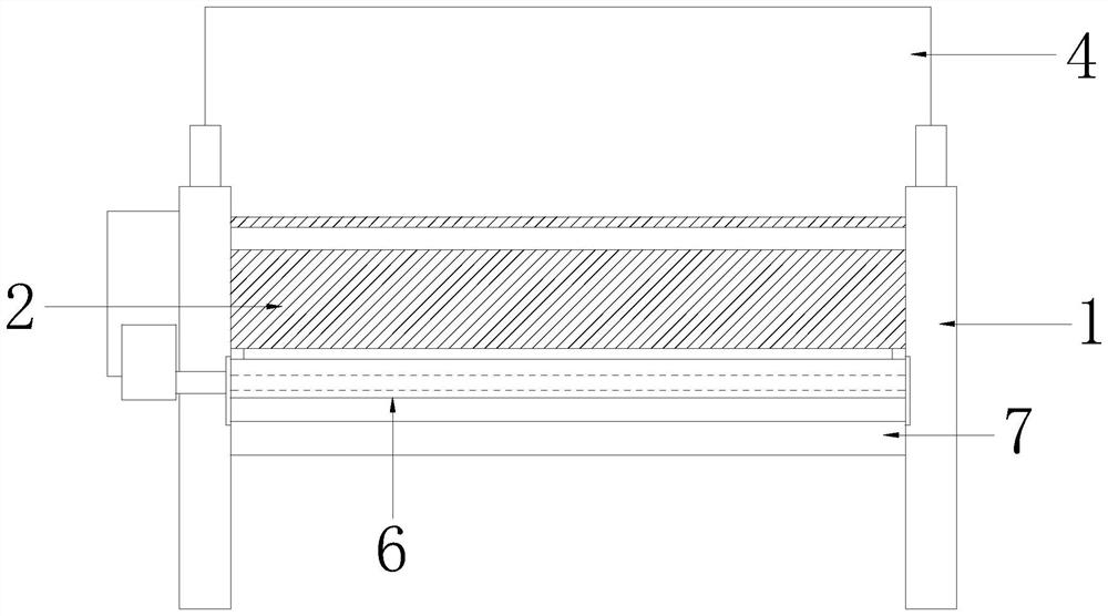
[0040] Such as Figure 6-Figure 7 As shown, the present invention provides a kind of technical scheme of glass blasting machine:

[0041] Such as Figure 6-Figure 7 As shown, a glass blasting machine, its structure includes the auxiliary desanding structure 6b including an arc net 6b1, a bomb seat 6b2, and a wiper head 6b3. 1-phase welding, the said spring seat 6b2 is provided with five pieces and is installed on the upper surface of the arc net 6b1 in a uniform and equidistant shape, and the said wiper head 6b3 is provided with five pieces and respectively matched with the upper surface of the spring seat 6b2, which is beneficial to Realize that the sand dust attached to the surface of the wiper cover 6b53 is frictionally shedding and matched.

[0042] Such as Figure 6 As shown, the combined height of the spring seat 6b2 and the wiping head 6b3 is in contact with the spring pressing rod 6a52, which is beneficial to realize the friction and shedding cooperation after conta...


PUM


Abstract

The invention discloses a sand blasting machine for glass. The sand blasting machine structurally comprises an equipment main body, a conveying belt, a sand blasting box, a dust remover, a sand returning box and an auxiliary dust removing device. The sand blasting machine has the beneficial effects that through an arranged surface belt cleaning mechanism, when an elastic pressing rod makes contactwith the surface of a conveying belt, the elastic pressing rod contracts backwards by a small section, and under cooperation of rotation of a sleeve shaft and transmission of the conveying belt, a wiping sleeve conducts stroking and wiping cooperation on sand and dust retained on the surface of the conveying belt, and abrasions of the bottom of the glass when the glass is placed on the upper surface, with the sand and dust retained, of the conveying belt are avoided; according to the sand blasting machine, an arranged auxiliary sand removing structure is matched with contact between the wiping head and the elastic pressing rod, the sand and dust attached to the surface of the wiping sleeve are subjected to friction falling treatment, and the phenomena that unnecessary grinding and scraping and incomplete cleaning are caused to the surface of the conveying belt due to the fact that the sand and dust are attached to the surface of the elastic pressing rod when the surface of the conveying belt is wiped again are avoided.

Description

technical field [0001] The invention relates to the field of glass processing equipment, more precisely, a glass sandblasting machine. Background technique [0002] Sand blasting machine, also known as sand making machine, is a frequently used sand processing equipment in the foundry machinery industry. [0003] In the glass processing technology, it is usually necessary to cooperate with a sand blasting machine to do sandblasting on the glass surface. Since the sand dust on the surface of the conveying plate cannot be completely cleaned, there will still be a small amount of sand dust and larger particles. When the glass is placed for the second time, the bottom of the glass is in contact with the sand and gravel, and the placement is unstable and the bottom of the glass is scratched during the transportation process. Contents of the invention [0004] Aiming at the deficiencies in the prior art, the object of the present invention is to provide a glass sandblasting mach...

Claims


Application Information

Patent Timeline
IPC IPC(8): B24C3/00B24C9/00
CPCB24C3/00B24C9/00B24C9/003
Inventor 陈福育
Owner 陈福育
Why Eureka
Try Eureka