
Robot for urban power grid tunnel dangerous environment

An urban power grid and robot technology, applied in the field of tunnel robots, can solve problems such as signal loss, limited camera angle adjustment, and hidden safety hazards, and achieve the effect of ensuring comprehensiveness, improving shooting range, and ensuring clarity.

Pending Publication Date: 2021-03-26
深圳市智美高科技有限公司
View PDF8 Cites 0 Cited by
  • Summary
  • Abstract
  • Description
  • Claims
  • Application Information

AI Technical Summary

Problems solved by technology

[0003] At present, after the power grid tunnel is completed, staff are required to check the internal environment of the tunnel and the operating status of the equipment on time. However, due to the complexity of the internal environment of the tunnel, there are likely to be certain safety hazards after the staff enters. Therefore, it is necessary to use tunnel robots to inspect the tunnel. Internal fixed inspection work, refer to comparative patent 1, the patent number is a robot inspection method for urban power grid tunnel dangerous environment disclosed by CN101446203B, refer to comparative patent 2, the patent number is a tunnel detection robot and detection method disclosed by CN105082180B, In the above-mentioned published patents, robots are used to inspect the tunnel, but the comparative patent 1 lacks a camera device for shooting inside the tunnel, and it is difficult for external staff to understand the internal conditions of the tunnel in real time. The angle adjustment of the camera is limited, and the shooting range inside the tunnel is limited, and dust is easy to adhere to the camera, which easily leads to unclear shooting, and cannot be automatically cleaned according to the image shooting situation, which will affect the inspection work. Internal signal shielding is strong, and signal loss is prone to occur, resulting in staff omissions in inspection operations

Method used


Image

  • Robot for urban power grid tunnel dangerous environment
  • Robot for urban power grid tunnel dangerous environment
  • Robot for urban power grid tunnel dangerous environment

Examples


Embodiment Construction

[0031] The present invention will be further described below in conjunction with the examples.

[0032] The following examples are used to illustrate the present invention, but cannot be used to limit the protection scope of the present invention. The conditions in the embodiment can be further adjusted according to the specific conditions, and the simple improvement of the method of the present invention under the premise of the concept of the present invention belongs to the protection scope of the present invention.

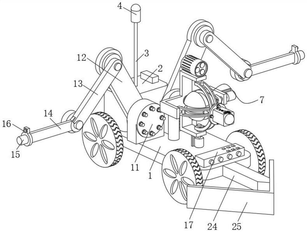
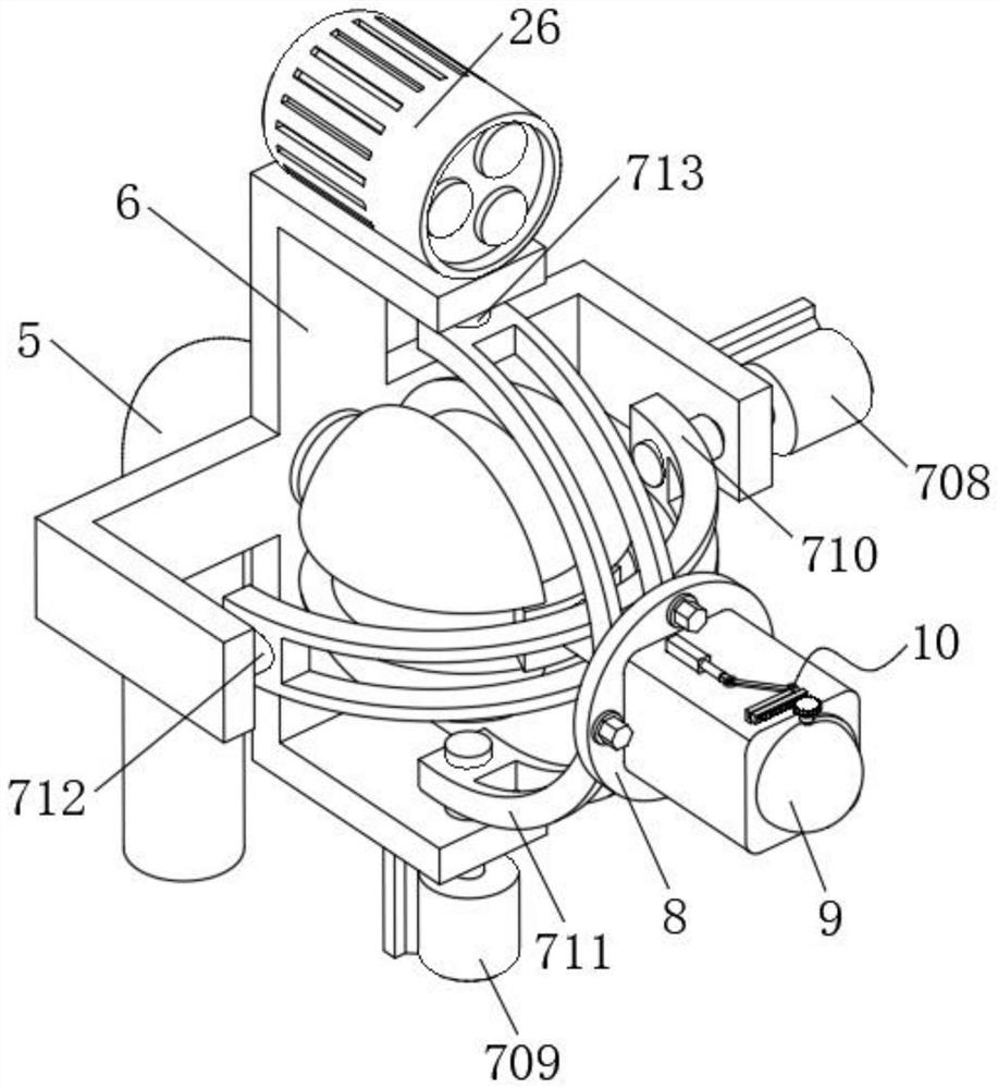
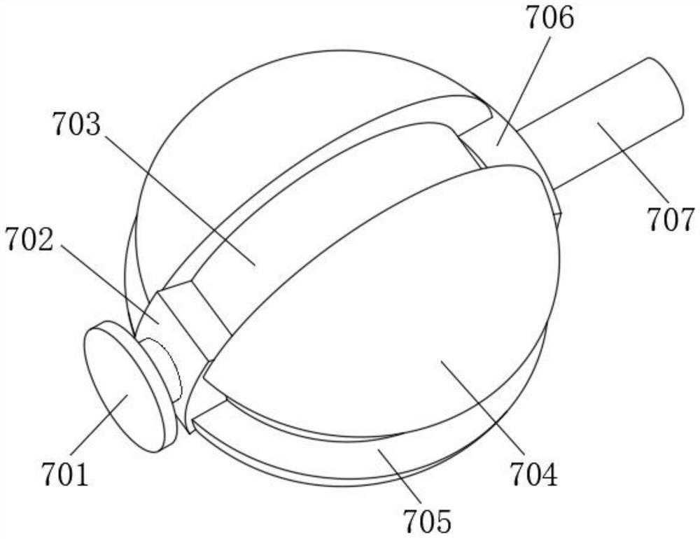
[0033] see Figure 1-7 , the present invention provides a robot for the dangerous environment of urban power grid tunnels, including a car body 1 and a driver 2 installed on the rear surface of the car body 1, a fixed rod 3 is fixedly connected to the driver 2, and the top end of the fixed rod 3 A signal amplifier 4 is installed on it (see figure 1 ); through the signal amplifier 4, the signal connection strength with the ground staff is enhanced to avoid si...


PUM


Abstract

The invention discloses a robot for an urban power grid tunnel dangerous environment, and belongs to the technical field of tunnel robots. The robot comprises a vehicle body and a driver installed onthe surface of the rear side of the vehicle body, wherein a stand column is fixedly connected to the vehicle body, an installation plate is fixedly connected to the stand column, and the installationplate is of a cross-shaped structure; and a multi-angle adjusting mechanism is mounted on the inner side wall of the installation plate, a connecting plate is fixedly connected to the multi-angle adjusting mechanism, and a video camera is mounted on the connecting plate. The video camera can be driven to steer in multiple directions, so that the shooting range of the video camera is enlarged, thecomprehensiveness of inspection work is ensured, and the definition of images shot by the camera is ensured; and meanwhile, a worker can check equipment through a camera on a mechanical arm c at a short distance, so that the abnormal condition of the equipment is known, the detection diversity is improved, the detection effect is better, data in a temporary memory in the camera can be called out independently, the data condition at the signal loss position is checked, and therefore omission is avoided.

Description

technical field [0001] The invention belongs to the technical field of tunnel robots, and in particular relates to a robot used in the dangerous environment of urban power grid tunnels. Background technique [0002] The power grid tunnel generally refers to the cable tunnel. The cable tunnel refers to the corridor or tunnel structure used to accommodate a large number of cables laid on the cable support. The cable tunnel not only allows the tunnel to better protect the cables, but also allows people to inspect the cables. and maintenance are very convenient. The advantages of the cable tunnel are many, the most obvious of which is that it is a one-time investment construction. There are many cable supports in the tunnel. Come up with a new plan. [0003] At present, after the power grid tunnel is completed, staff are required to check the internal environment of the tunnel and the operating status of the equipment on time. However, due to the complexity of the internal envi...

Claims


Application Information

Patent Timeline
Patent Type & Authority Applications(China)
IPC IPC(8): B25J11/00B25J5/00B25J19/00G01D21/02
CPCB25J5/007B25J11/00B25J19/0058G01D21/02
Inventor 崔华李刚
Owner 深圳市智美高科技有限公司
Learn More