Slicing device for food processing

A slicing device and food processing technology, applied in metal processing and other directions, can solve the problems of low slicing efficiency, uneven thickness, time-consuming and labor-intensive, etc., and achieve the effect of saving time, slicing consistent thickness and avoiding rust on the blade

Active Publication Date: 2021-03-26
佛山市功匠电器科技有限公司
View PDF4 Cites 1 Cited by
  • Summary
  • Abstract
  • Description
  • Claims
  • Application Information

AI Technical Summary

Problems solved by technology

[0004] In order to overcome the shortcomings of time-consuming and laborious, low slicing efficiency, and uneven thickness, the technical problem to be solved is to provide a food processing and slicing device with high processing efficiency, low labor intensity, consistent and adjustable slice thickness

Method used


Image

  • Slicing device for food processing
  • Slicing device for food processing
  • Slicing device for food processing

Examples


Embodiment 1

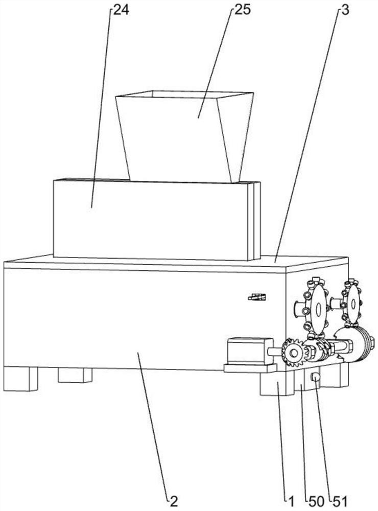
[0029] A food processing slicing device, such as Figure 1-6 As shown, it includes a base 1, a casing 2, a cover 3, a power mechanism, a pushing mechanism and a cutting mechanism. The casing 2 is fixedly installed above the four bases 1. Above the shell 2, the power mechanism is installed on the right side of the shell 2, the pushing mechanism is installed on the front side of the shell 2 inside, and the cutting mechanism is installed on the rear side of the shell 2 inside.

[0030] The base 1 supports the entire device, the outer shell 2 plays a fixed role, and the installation of the cover plate 3 protects the mechanism inside the outer shell 2 to prevent dust from falling into the outer shell 2. When the food is sliced, it passes through the power mechanism Drive the pushing mechanism to push the food to be sliced ​​forward, and then slice the food by the cutting mechanism.

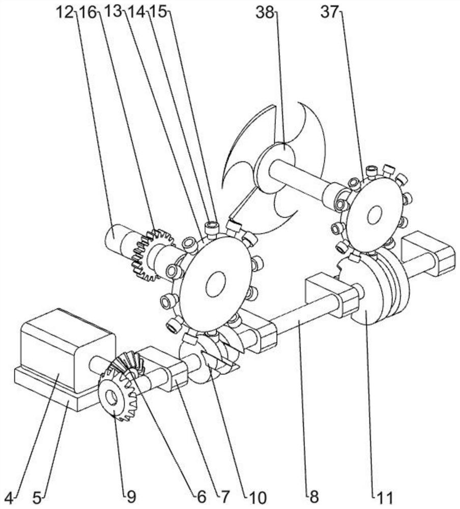
[0031] The power mechanism includes a motor 4, a support plate 5, a first cone wheel 6, a rectangu...

Embodiment 2

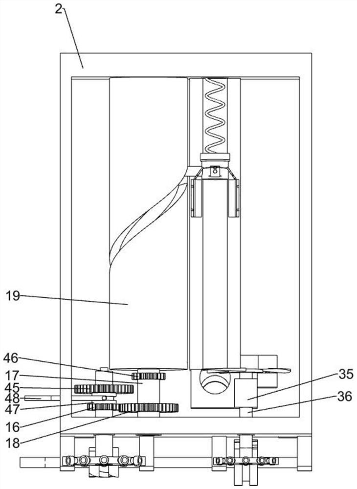
[0038] On the basis of Example 1, such as figure 1 , Figure 7-9 As shown, it also includes a blanking box 25, a first spring 26, a top plate 27, a third shaft 28, a push rod 29, a spring bar 30, a second connecting column 31, a fourth shaft 32, a supporting plate 33 and a second spring 34. The lower material box 25 is installed above the feed port 24, the circular hole on the feed port 24 has a rectangular slot, the top plate 27 is installed in the rectangular slot on the feed port 24, and the top plate 27 is installed on both sides. Three shafts 28, the top plate 27 is rotatably connected with the rectangular groove on the feed port 24 through the third shaft 28, the first spring 26 is installed between the rectangular groove and the top plate 27, the top plate 27 is in contact with the push column 20, and the upper left side of the top plate 27 Rotation is installed with push rod 29, and push rod 29 tops are in the rectangular groove above, and push rod 29 is connected wit...


PUM


Abstract

The invention relates to a slicing device, in particular to a slicing device for food processing. The slicing device for food processing is high in processing efficiency, low in labor intensity and consistent and adjustable in slicing thickness. According to the technical scheme, the slicing device for food processing comprises bases, a shell, a cover plate, a power mechanism, a pushing mechanism,a cutting mechanism and the like; and the shell is fixedly installed above the four bases and plays a role in fixing the whole device, the cover plate is installed above the shell, the power mechanism is installed on one side of the shell, the pushing mechanism is installed on one side of the interior of the shell, and the cutting mechanism is installed on the other side of the interior of the shell. The slicing device is provided with the power mechanism and the pushing mechanism, the power mechanism is matched with the pushing mechanism, food to be cut is pushed out at a constant speed, cutting is conducted while conveying is achieved, the slicing thickness is consistent, a speed changer is further arranged in the pushing mechanism, and the cutting thickness is changed by adjusting thespeed changer.

Description

technical field [0001] The invention relates to a slicing device, in particular to a food processing slicing device. Background technique [0002] At present, there is no synchronous conveying and slicing device on the market. Most slicing mechanisms can only do simple up and down reciprocating movements to cut the food. After each cutting, the position of the food to be cut needs to be rearranged. When slicing, it is necessary to reciprocally place the food according to the law of the movement of the slicing mechanism, and the thickness of the cut slices is uneven, which affects the quality and efficiency of food slicing. [0003] Therefore, there is an urgent need to develop a food processing and slicing device that can slice food while conveying, improve work efficiency, and have consistent and adjustable slice thickness. Contents of the invention [0004] In order to overcome the shortcomings of time-consuming and laborious, low slicing efficiency, and uneven thicknes...

Claims


Application Information

Patent Timeline
Patent Type & Authority Applications(China)
IPC IPC(8): B26D7/08B26D7/18B26D7/32
CPCB26D7/1818B26D7/088B26D7/32
Inventor 李美霞
Owner 佛山市功匠电器科技有限公司
Why Eureka
Try Eureka