Supercharge Your Innovation With Domain-Expert AI Agents!

Adjusting structure of upper pressing roller of veneering machine

A technology for adjusting structures and laminating machines, which is applied in the direction of container manufacturing machinery, envelope/bag manufacturing machinery, rigid/semi-rigid container manufacturing, etc., and can solve the problems of tediousness and low precision

Inactive Publication Date: 2021-03-26
芜湖恒丰彩印包装股份有限公司
View PDF0 Cites 0 Cited by
  • Summary
  • Abstract
  • Description
  • Claims
  • Application Information

AI Technical Summary

Problems solved by technology

[0005] Aiming at the deficiencies of the prior art, the present invention provides an adjustment structure for the upper pressure roller of the veneer machine, which solves the problem of low precision and cumbersome problems in manual adjustment of the upper pressure roller

Method used


Image

  • Adjusting structure of upper pressing roller of veneering machine
  • Adjusting structure of upper pressing roller of veneering machine
  • Adjusting structure of upper pressing roller of veneering machine

Examples


Embodiment Construction

[0024] The following will clearly and completely describe the technical solutions in the embodiments of the present invention with reference to the accompanying drawings in the embodiments of the present invention. Obviously, the described embodiments are only some, not all, embodiments of the present invention. Based on the embodiments of the present invention, all other embodiments obtained by persons of ordinary skill in the art without making creative efforts belong to the protection scope of the present invention.

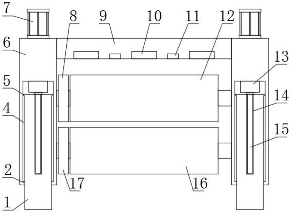
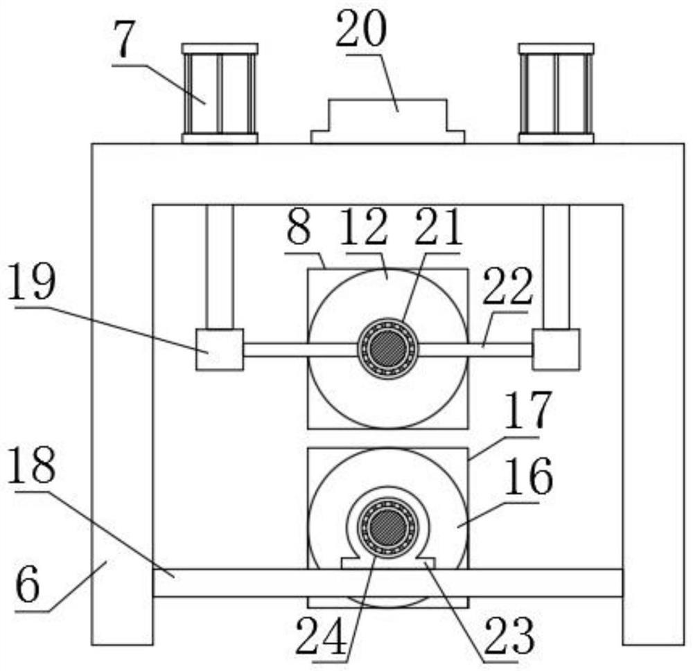
[0025] Such as Figure 1-3 As shown, the present invention provides a technical solution: an adjustment structure for pressing rollers on a veneer machine, including two U-shaped frames 6 symmetrically distributed left and right. And the upper surface of the U-shaped frame 6 is located between the two electric telescopic rods 7 and a relay 20 is fixed, and the bottom ends of the output shafts of the two electric telescopic rods 7 run through the upper surface ...


PUM


Abstract

The invention relates to the technical field of veneering machines, and discloses an adjusting structure of an upper pressing roller of a veneering machine. The adjusting structure of the upper pressing roller of the veneering machine comprises two U-shaped frames distributed in a bilateral symmetry mode, wherein electric telescopic rods are fixed to the upper surfaces of the U-shaped frames in afront-back symmetry mode; relays are fixed to the parts, located between the two electric telescopic rods, of the upper surfaces of the U-shaped frames; the bottom ends of output shafts of the two electric telescopic rods penetrate through the upper surfaces of the U-shaped frames; connecting blocks are fixed to the bottom ends of the output shafts of the two electric telescopic rods; connecting rods are fixed to the opposite sides of the two connecting blocks; and first bearings are fixed to the opposite ends of the two connecting rods. An infrared temperature sensor and a micro-current sensor can monitor the surrounding environment in real time, when the infrared temperature sensor and the micro-current sensor monitor that a human hand approaches, a signal is sent to a single-chip microcomputer, then the single-chip microcomputer sends the signal to main control equipment of the veneering machine, and at the moment, the main control equipment immediately controls the veneering machine to stop running, so that the situation that people are hurt is avoided.

Description

technical field [0001] The invention relates to the technical field of veneer machines, in particular to an adjustment structure for pressure rollers on a veneer machine. Background technique [0002] Packaging refers to the overall name of containers, materials and auxiliary materials used according to certain technical methods to protect products during circulation, facilitate storage and transportation, and promote sales. With the rise of online shopping and the rapid development of the express delivery industry, it is necessary to A large number of packaging boxes are used to package the products. During the production process of the packaging boxes, in order to ensure the quality and aesthetics of the packaging boxes, the raw materials of the packaging boxes are often processed by a laminating machine. [0003] When the existing veneer is processing the raw materials of the packaging box, when the upper pressing roller is adapted to the raw material of the packaging box...

Claims


Application Information

Patent Timeline
IPC IPC(8): B31B50/59B31B50/74
CPCB31B50/59B31B50/74
Inventor 宗胜光
Owner 芜湖恒丰彩印包装股份有限公司
Features
  • R&D
  • Intellectual Property
  • Life Sciences
  • Materials
  • Tech Scout
  • Unparalleled Data Quality
  • Higher Quality Content
  • 60% Fewer Hallucinations
Learn More