
Chip mounting device

A patch device and a one-to-one correspondence technology, applied in the field of patch manufacturing, can solve problems such as quality problems, and achieve the effect of improving patch efficiency and quality

Pending Publication Date: 2021-03-26
武汉乾峯智能科技有限公司
View PDF0 Cites 0 Cited by
  • Summary
  • Abstract
  • Description
  • Claims
  • Application Information

AI Technical Summary

Problems solved by technology

[0003] The main purpose of the present invention is to propose a placement device, which aims to solve the quality problems existing in traditional manual placement

Method used


Image

  • Chip mounting device
  • Chip mounting device
  • Chip mounting device

Examples


Embodiment Construction

[0031] The following will clearly and completely describe the technical solutions in the embodiments of the present invention with reference to the accompanying drawings in the embodiments of the present invention. Obviously, the described embodiments are only part of the embodiments of the present invention, not all of them. Based on the embodiments of the present invention, all other embodiments obtained by persons of ordinary skill in the art without creative efforts fall within the protection scope of the present invention.

[0032] It should be noted that if there is a directional indication (such as up, down, left, right, front, back...) in the embodiment of the present invention, the directional indication is only used to explain the position in a certain posture (as shown in the accompanying drawing). If the specific posture changes, the directional indication will also change accordingly.

[0033] In addition, if there are descriptions involving "first", "second" and ...


PUM


Abstract

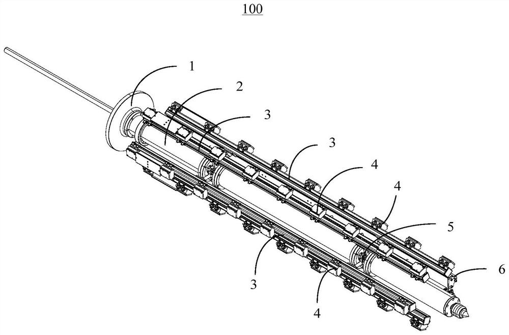
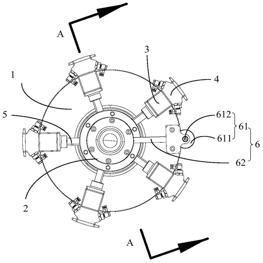
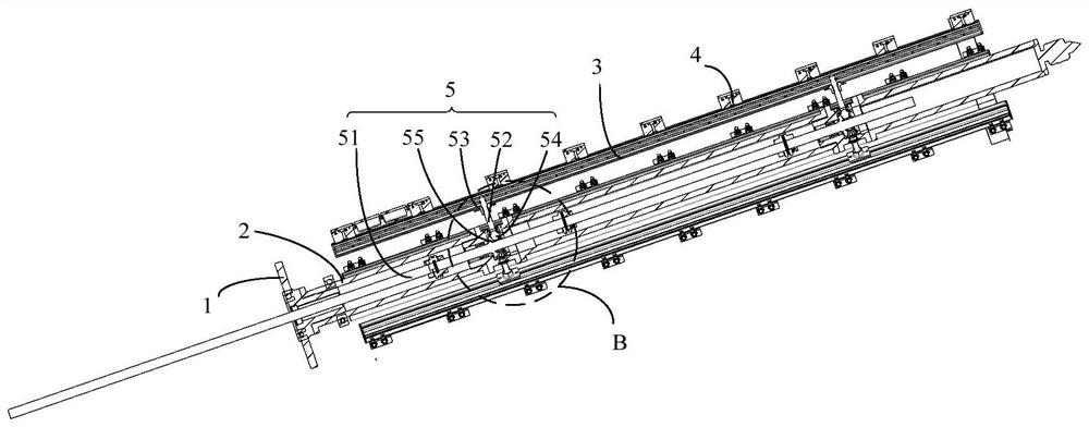
The invention discloses a chip mounting device, which comprises a seat body, a main shaft, a plurality of support rods, a plurality of sucker assemblies and a driving device, and is characterized in that the main shaft is rotatably arranged on the seat body along the axis direction; the support rods are arranged at intervals in the circumferential direction of the main shaft, and each support rodextends in the axial direction of the main shaft and is telescopically arranged on the outer side wall of the main shaft in the radial direction. The sucker assemblies correspond to the support rods,and a plurality of suckers in each sucker assembly are distributed on the corresponding supporting rod at intervals in the length direction of the support rod. A first driving assembly in the drivingdevice drives the main shaft to rotate, and a second driving assembly drives the supporting rod to stretch. A chip is fixed through the sucker, the main shaft drives the support rod to rotate to automatically roll the chip and eliminate pulling of the chip, after the supporting rod rotates by a circle, the chip is rolled into the diameter of a combustion chamber, then the support rod retracts in the radial direction of the main shaft and is fed into the combustion chamber, the support rod extends to the chip to be pasted to the inner wall of the combustion chamber and extrudes the chip, and the defects of wrinkles, cracking and the like are eliminated.

Description

technical field [0001] The invention relates to the technical field of patch manufacturing, in particular to a patch device. Background technique [0002] The heat insulation layer is an important part of the solid rocket motor, which can prevent the shell of the charge combustion chamber from losing strength or being burned through due to high temperature under the action of high-temperature gas, and plays a very important role in the safety and reliability of the engine. , the traditional manufacturing process of the inner insulation layer of the solid rocket motor adopts the manual patching process, that is, in the process of making the insulation layer of the large-diameter engine, the operator enters the charge combustion chamber for manual patch construction, and pastes high-temperature-resistant insulating materials in the combustion chamber patch, so as to ensure that the heat insulation layer of different parts in the charge combustion chamber meets the requirements...

Claims


Application Information

Patent Timeline
IPC IPC(8): B32B37/00B32B37/10
CPCB32B37/0015B32B37/0053B32B37/10
Inventor 陈俊李卫韩丰叶成潘红涛李海波曾敏严沛张红相
Owner 武汉乾峯智能科技有限公司
Learn More