Vehicle body and rubber-tired train

A car body and train technology, which is applied to the upper structure of motor vehicles, vehicle components, and passenger cars, can solve problems such as stress concentration and uneven distribution of braking force, and achieve the effects of avoiding stress concentration and reducing load

Active Publication Date: 2021-03-26
CRRC NANJING PUZHEN CO LTD
View PDF7 Cites 1 Cited by
  • Summary
  • Abstract
  • Description
  • Claims
  • Application Information

AI Technical Summary

Problems solved by technology

[0004] The embodiment of the present application provides a car body and a rubber-tyred train, which is mainly used to solve the problems of uneven distribution of braking force and stress concentration on the end wall of the car body in the related art

Method used


Image

  • Vehicle body and rubber-tired train
  • Vehicle body and rubber-tired train
  • Vehicle body and rubber-tired train

Examples


Embodiment 1

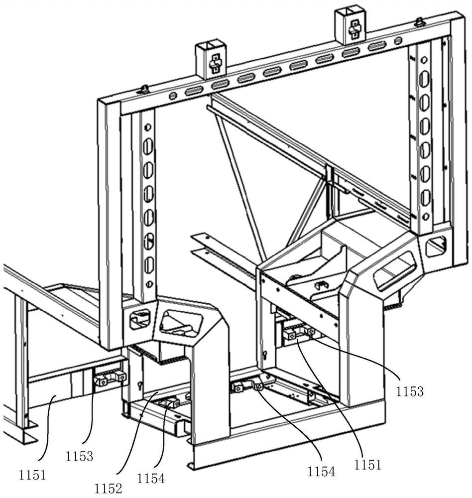
[0038] This embodiment provides a car body, which is applied to a low-floor train with rubber tires, and includes an underframe and a top plate oppositely arranged, and a car body side wall and a car body end wall connecting the under frame and the top plate, wherein the above car body It can be a motor car body or an intermediate car body. For the convenience of description, this embodiment takes the connection structure between the motor car body and the trailer bogie as an example for illustration. It is clear to those skilled in the art that the connection structure between the intermediate car body and the trailer bogie is exactly the same as the connection structure between the motor car body and the trailer bogie, and will not be repeated in this embodiment. The car body end wall is used to connect the trailer traction device on the trailer bogie to transmit traction or braking force between the trailer bogie and the motor car body, and to adapt to the relative movement ...

Embodiment 2

[0061] This embodiment provides a rubber-tyred train, which includes a plurality of end-to-end carriages. The car bodies of the carriages are as described in the first embodiment above, and two adjacent car bodies are connected by trailer bogies.

[0062] Since the rubber-tyred train of this embodiment adopts the car body described in the first embodiment above, it can utilize two first traction assemblies and two second traction assemblies to jointly transmit the tractive force and control between the trailer bogie and the car body. Power reduces the load on each towing component, while evenly distributing traction and braking forces to the entire car body frame and trailer bogie to avoid stress concentration.

[0063] Figure 8 Shown in is a schematic diagram of the connection structure between the trailer bogie and the vehicle body provided by an embodiment of the present application; Figure 9 Shown in is a schematic structural diagram of the trailer traction device provi...


PUM


Abstract

The embodiment provides a train body and a rubber-tired train, the train body comprises a bottom frame and a top plate which are oppositely arranged, and a train body side wall and a train body end wall which are connected with the bottom frame and the top plate, the train body end wall comprises two train end outer side cross beams and a train end inner side cross beam, and in the width directionof the train body, the train end inner side cross beam is located between the two train end outer side cross beams; a first vehicle body traction rod seat is arranged on each vehicle end outer side cross beam and is perpendicular to the vehicle body end wall; two second vehicle body traction rod seats are arranged on the vehicle end inner side cross beam, and the second vehicle body traction rodseats are obliquely arranged away from the adjacent first vehicle body traction rod seats. The vehicle body end wall is connected with the two first traction assemblies and the two second traction assemblies at the same time so as to transmit traction force and braking force between the trailer bogie and the vehicle body together, the load on each traction assembly is reduced, meanwhile, the traction force and the braking force are evenly distributed to the whole vehicle body end wall, and the situation of stress concentration is avoided.

Description

technical field [0001] The present application relates to the manufacturing technology of rubber-tyred trains, in particular to a car body and rubber-tyred trains. Background technique [0002] With the development of urban traffic construction, articulated trains (such as traditional low-floor trolleybuses, urban BRT trains, etc.) are gradually put into use to relieve road traffic pressure. An articulated train is a wheeled train composed of two or more carriages connected together by a hinge device. The articulated train changes its forward direction by the guidance of the hinge device between the carriages. [0003] In an articulated train, the traction and braking forces between two adjacent carriages are transmitted by the traction device on the bogie. However, in the solutions of related technologies, problems such as uneven distribution of braking force and stress concentration are prone to occur at the connection between the end wall of the vehicle body and the trac...

Claims


Application Information

Patent Timeline
Patent Type & Authority Applications(China)
IPC IPC(8): B62D31/02B62D47/02B60D1/48
CPCB62D31/02B62D47/025B60D1/48Y02T30/00
Inventor 董静张晓珍王媛媛刘英博欧士玺姜琨久
Owner CRRC NANJING PUZHEN CO LTD
Why Eureka
Try Eureka