Wheeled leg robot and driving method thereof

A wheel-legged robot and thigh technology, which is used in motor vehicles, transportation and packaging, etc., can solve the problems of low effective energy utilization rate of robots, large throttling power loss, hydraulic components and seal damage, etc.

Active Publication Date: 2021-03-26
北京理工大学重庆创新中心 +1
View PDF12 Cites 0 Cited by
  • Summary
  • Abstract
  • Description
  • Claims
  • Application Information

AI Technical Summary

Problems solved by technology

[0005] 1. The servo valve control cylinder realizes precise output force/speed control of the hydraulic cylinder through the throttling of the servo valve. There is a large throttling power loss, the transmission efficiency of the hydraulic system is low, and the effective energy utilization rate of the robot is low.
[0006] 2. The servo valve control cylinder is a rigid actuator composed of a servo valve an...

Method used


Image

  • Wheeled leg robot and driving method thereof
  • Wheeled leg robot and driving method thereof
  • Wheeled leg robot and driving method thereof

Examples


Embodiment 1

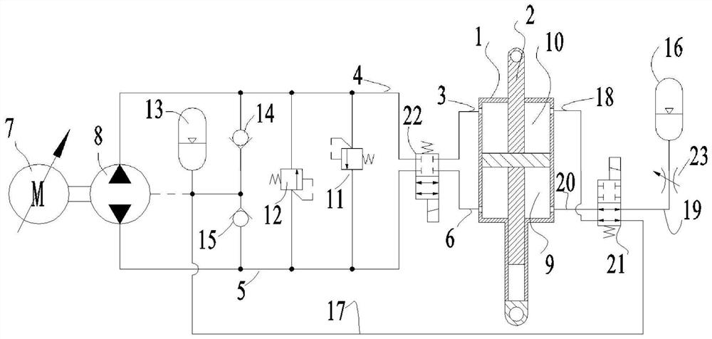
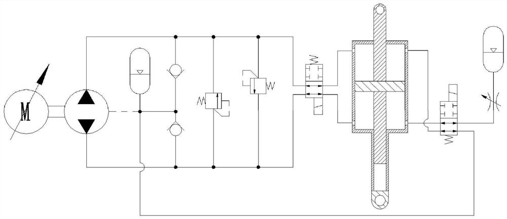
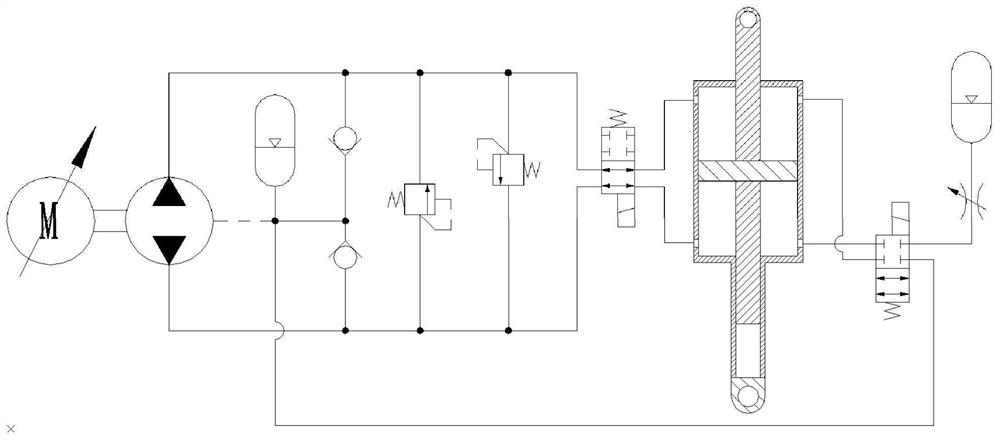
[0029] See attached Figure 1~5. A wheel-legged robot comprises a car body 35, a thigh 36, a calf 37, a wheel 38 and two hydraulic control systems; one end of the thigh 36 is hinged to the car body 35, and the other end of the thigh 36 is hinged to one end of the calf 37; the calf The other end of 37 is provided with wheel 38; two hydraulic control systems respectively control the size of the included angle between the car body 35 and the thigh 36, and the size of the included angle between the thigh 36 and the shank 37; the hydraulic control system includes hydraulic cylinder 1, Piston rod 2, oil supplement accumulator 13, high-pressure accumulator 16, high-pressure oil circuit and low-pressure oil circuit; the hydraulic cylinder 1 is provided with a bearing chamber 9 and a non-bearing chamber 10; the piston rod 2 separates the bearing chamber 9 and the non-bearing chamber 10; the outlet of the charge accumulator 13 communicates with the non-bearing chamber 10 through a low-...

Embodiment 2

[0031] See attached Figure 1~5 . On the basis of the first embodiment, the hydraulic control system further includes a second solenoid valve 21; the low-pressure oil circuit includes the fifth oil circuit 17 and the sixth oil circuit 18; the high-pressure oil circuit includes the seventh oil circuit 19 and the eighth oil circuit 20; the second electromagnetic valve 21 is a two-position four-way electromagnetic switch valve; the second electromagnetic valve 21 includes a2 port, b2 port, c2 port and d2 port; the fifth oil circuit 17 Both ends of the sixth oil passage 18 are respectively connected to the b2 port and the non-bearing chamber 10; both ends of the seventh oil passage 19 are respectively connected to the c2 port and the high-pressure accumulator device 16; both ends of the eighth oil passage 20 are respectively connected to the d2 port and the bearing chamber 9; when the second solenoid valve 21 is in the off-potential state, except that the a2 port is connected to ...

Embodiment 3

[0039] See attached Figure 1~5. A method for driving a wheel-legged robot, using the wheel-legged robot described in Embodiment 1, including a passive vibration reduction step; the passive vibration reduction step specifically includes: driving the wheel-legged robot to drive when the wheel 38 touches the ground and rotates; The low-pressure oil circuit is conducted, and the outlet of the charge accumulator 13 communicates with the non-bearing chamber 10 through the low-pressure oil circuit; the high-pressure oil circuit is conducted, and the outlet of the high-pressure accumulator 16 passes through the high-pressure oil circuit and the bearing chamber 9 communication; the hydraulic oil between the bearing chamber 9 and the non-bearing chamber 10 is not exchanged; when the wheel-legged robot is driving on a flat ground, the load force borne by the hydraulic cylinder 1 and the piston rod 2 has no fluctuation, the car body 35 has no vibration, and the piston The relative elong...


PUM


Abstract

The invention discloses a wheeled leg robot and a driving method thereof, and belongs to the technical field of wheeled leg robots, the wheeled leg robot comprises a vehicle body, thighs, shanks, wheels and two hydraulic control systems; one end of the thigh is hinged with the vehicle body, and the other end is hinged with one end of the shank; wheels are arranged at the other ends of the shanks;the two hydraulic control systems respectively control the included angle between the vehicle body and the thigh and the included angle between the thigh and the shank; the hydraulic control system comprises a hydraulic cylinder, a piston rod, an oil supplementing energy accumulator, a high-pressure energy accumulator, a high-pressure oil way and a low-pressure oil way. A bearing cavity and a non-bearing cavity are formed in the hydraulic cylinder; the piston rod separates the bearing cavity from the non-bearing cavity; an outlet of the oil supplementing energy accumulator communicates with the non-bearing cavity through a low-pressure oil way. An outlet of the high-pressure energy accumulator communicates with the bearing cavity through a high-pressure oil way. According to the wheeled leg robot and the driving method thereof, large throttling power loss is avoided, the transmission efficiency of a hydraulic system is high, the energy utilization rate is high, the buffering performance is good, and the service life is long.

Description

technical field [0001] The invention belongs to the technical field of wheel-leg robots, and in particular relates to a wheel-leg robot and a driving method thereof. Background technique [0002] The wheel-legged robot refers to adding wheels to the end of the robot legs. This kind of robot fully combines the advantages of wheels and legs. pass in a structured environment. Compared with the legged robot, it has a faster traveling speed in the road environment, so the research on the wheel-legged robot has received more and more attention. [0003] At present, research on wheel-legged robots is mainly focused on small wheel-legged robot platforms. The robot body and load capacity are small, and the combination of motor and reducer can be used to drive the leg joints; for medium / large wheel-legged robots The drive of the leg joints is driven by a servo valve control cylinder. The servo valve is installed on the hydraulic cylinder, and the piston rod of the hydraulic cylinder...

Claims


Application Information

Patent Timeline
IPC IPC(8): B62D57/028
CPCB62D57/028
Inventor 胡小东徐彬秦也辰刘辉项昌乐杨海洋刘春桃
Owner 北京理工大学重庆创新中心
Why Eureka
Try Eureka