Water seepage system for sponge city

A sponge city and water-liquid technology, applied in waterway systems, sewage removal, water supply devices, etc., can solve the problems of poor structural strength and short service life of permeable bricks, and achieve the effect of avoiding water accumulation and restoring ecological damage

Pending Publication Date: 2021-03-26
基准方中建筑设计股份有限公司
View PDF0 Cites 0 Cited by
  • Summary
  • Abstract
  • Description
  • Claims
  • Application Information

AI Technical Summary

Problems solved by technology

[0004] The purpose of the present invention is to overcome the disadvantages of poor structural strength and short service life of permeable bricks in the prior art, and provide a sponge city water seepage system with good water seepage effect and high water seepage reliability

Method used


Image

  • Water seepage system for sponge city
  • Water seepage system for sponge city
  • Water seepage system for sponge city

Examples


Embodiment 1

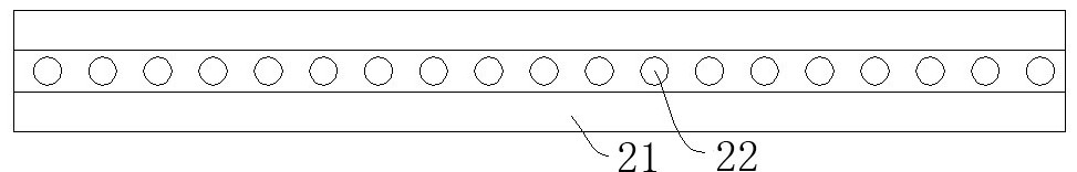
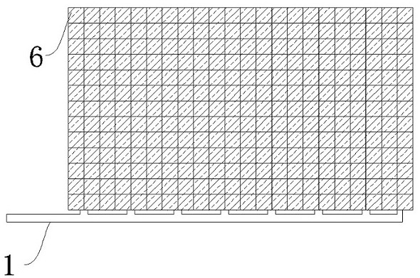
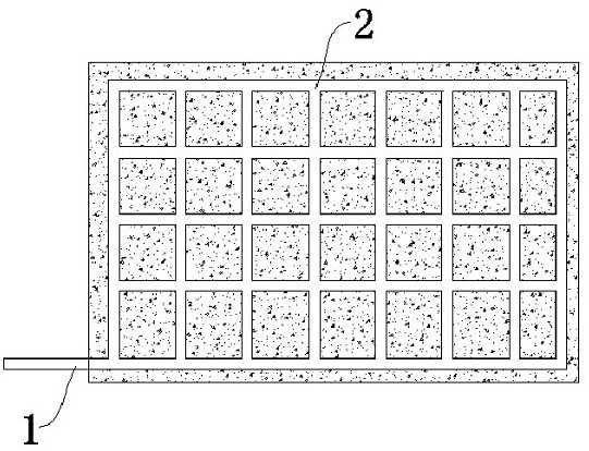
[0039] like figure 1 and figure 2 As shown, a water seepage system for a sponge city includes a water seepage blind ditch 2, a water seepage cover plate and a surface layer 6, the water seepage blind ditch 2 converges into a network structure, and a number of water seepage blind ditch 2 is opened on the base layer 9, and the water seepage blind ditch 2 Covered by the seepage cover plate, and the seepage joint 5 where the water liquid flows into the seepage blind ditch 2 is left on the seepage cover plate, and the surface layer 6 is laid on the seepage cover plate, and the surface layer 6 is left corresponding to the seepage joint 5 The water liquid on the surface layer 6 flows into the seepage blind ditch 2 through the stitching seam and the water seepage joint 5 successively.

[0040] In this example, if Image 6 As shown, a plain soil layer 17 is laid on the base layer 9 in the seepage blind ditch 2, a second water seepage layer 11 is laid on the plain soil layer 17, a fi...

Embodiment 2

[0049] like figure 1 and figure 2 As shown, a water seepage system for a sponge city includes a water seepage blind ditch 2, a water seepage cover plate and a surface layer 6, the water seepage blind ditch 2 converges into a network structure, and a number of water seepage blind ditch 2 is opened on the base layer 9, and the water seepage blind ditch 2 Covered by the seepage cover plate, and the seepage joint 5 where the water liquid flows into the seepage blind ditch 2 is left on the seepage cover plate, and the surface layer 6 is laid on the seepage cover plate, and the surface layer 6 is left corresponding to the seepage joint 5 The water liquid on the surface layer 6 flows into the seepage blind ditch 2 through the stitching seam and the water seepage joint 5 successively.

[0050] In this example, if Figure 12 As shown, a plain soil layer 17 is laid on the base layer 9 in the seepage blind ditch 2, a second water seepage layer 11 is laid on the plain soil layer 17, a ...


PUM


Abstract

The invention discloses a water seepage system for a sponge city. The system comprises water seepage blind ditches, a water seepage cover plate and a surface layer, the water seepage blind ditches intersect to form a net structure, a plurality of water seepage blind ditches are formed in a base layer and covered with the water seepage cover plate, water seepage seams allowing water to flow into the water seepage blind ditches are reserved in the water seepage cover plate, the surface layer is laid on the water seepage cover plate, splicing seams corresponding to the water seepage seams are reserved in the surface layer, and water on the surface layer sequentially passes through the splicing seams and the water seepage seams to flow into the water seepage blind ditches. The water seepage system has the beneficial effects that the water seepage cover plate is designed in a hidden mode, the attractiveness of a driving area and a pedestrian area cannot be affected under the effect of a water seepage function, rainwater can be drained into the water seepage blind ditch in time through the water seepage structure, then the rainwater infiltrates into an underground water system under natural soil through the water seepage blind ditch, ecological damage to underground water in a local area during restoration construction is avoided, and meanwhile water accumulation in pedestrian and driving areas of a high-end community is avoided.

Description

technical field [0001] The invention relates to a water seepage system, in particular to a water seepage system for a sponge city. Background technique [0002] In the existing seepage system that uses permeable bricks to pave the pedestrian and vehicle areas, in order to ensure the water seepage effect, the structural strength of the permeable bricks is low, and it is easy to be damaged during use, thus affecting the effect of the pedestrian and vehicle areas , unable to meet the requirements of high-end community pedestrian or vehicle areas with high-end landscape quality positioning. [0003] After long-term research, the inventors of our company have excluded areas that are prone to structural collapse such as "groundwater level -1.00 meters, serious runoff pollution, collapsible loess or expansive soil, and are less than 3m away from the building foundation in the horizontal direction". A water seepage system was developed to meet the requirements of pedestrian or vehi...

Claims


Application Information

Patent Timeline
Patent Type & Authority Applications(China)
IPC IPC(8): E01C11/22E03F1/00
CPCE01C11/22E01C11/224E01C11/227E03F1/002
Inventor 赵东亚江冰莲
Owner 基准方中建筑设计股份有限公司
Why Eureka
Try Eureka