Light-emitting part and manufacturing method thereof
A manufacturing method and technology for light-emitting parts, which are applied in the field of handicrafts or furniture, can solve the problems of being inflexible and lacking, and achieve the effects of easy installation and production, simple structure and low production cost.
- Summary
- Abstract
- Description
- Claims
- Application Information
AI Technical Summary
Problems solved by technology
Method used
Image

Examples
Embodiment Construction
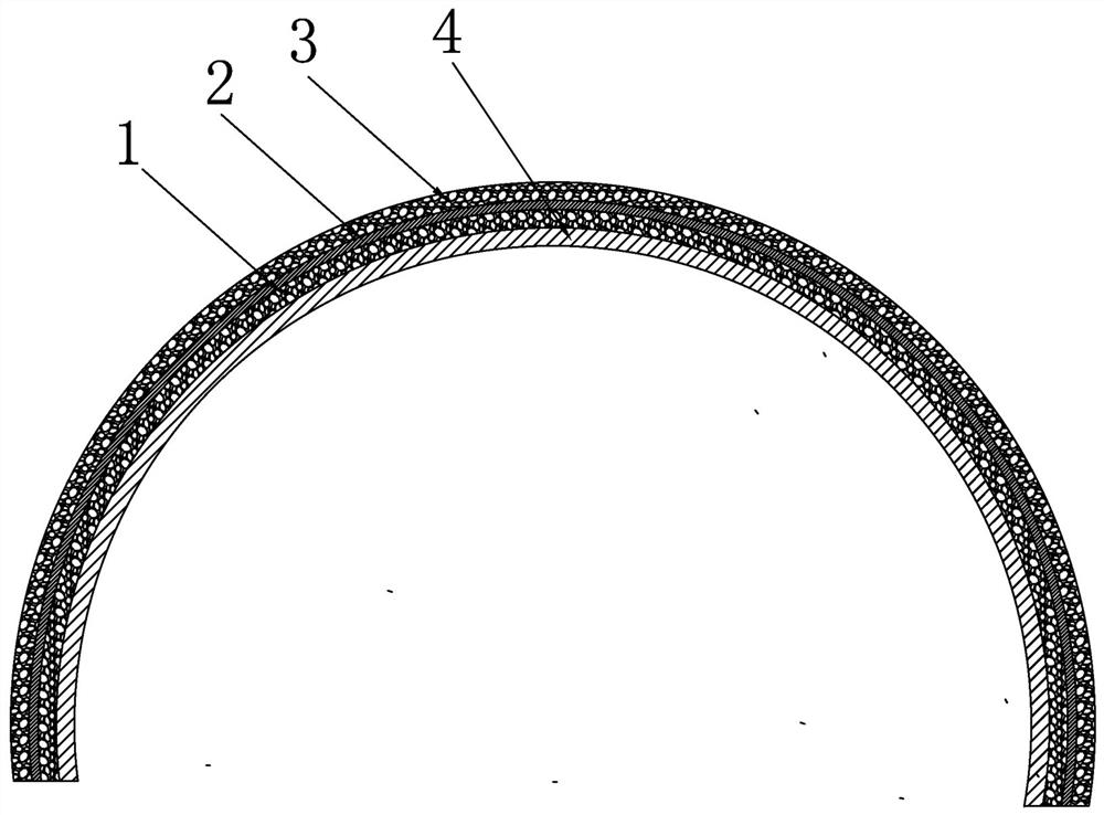
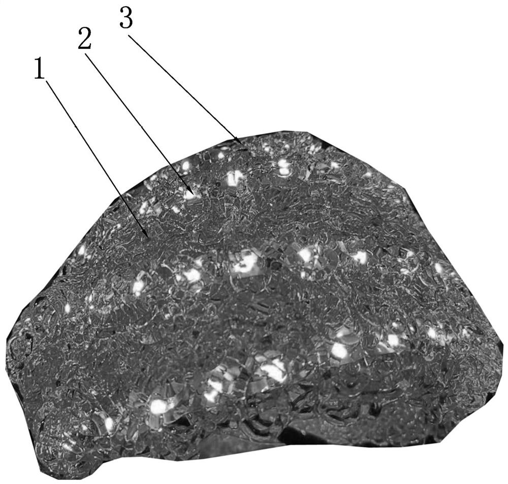
[0019] The present invention will be specifically and further described below in conjunction with the accompanying drawings. A light-emitting element, characterized in that it comprises a hot-melt supporting skeleton layer 1 made of light-guiding material, a light-emitting element 2 covering the surface of the hot-melt supporting skeleton layer 1, and the surface of the light-emitting element 2 is covered with a light-guiding material The hot-melt surface layer 3 is produced, and the light-emitting element 2 is clamped and fixed between the hot-melt surface layer 3 and the hot-melt supporting skeleton layer 1 .
[0020] The light-emitting element 2 is an LED strip.
[0021] The light-emitting element 2 is an LED lamp string.
[0022] The hot-melt supporting frame layer 1 and the hot-melt surface layer 3 are made of light-transmitting or reflective plastic threads.
[0023] Each of the hot-melt support skeleton layer 1 and the hot-melt surface layer 3 can be composed of one l...
PUM
 Abstract
Description
Claims
Application Information
 - Generate Ideas
- Intellectual Property
- Life Sciences
- Materials
- Tech Scout
- Unparalleled Data Quality
- Higher Quality Content
- 60% Fewer Hallucinations
Browse by: Latest US Patents, China's latest patents, Technical Efficacy Thesaurus, Application Domain, Technology Topic, Popular Technical Reports.
© 2025 PatSnap. All rights reserved.Legal|Privacy policy|Modern Slavery Act Transparency Statement|Sitemap|About US| Contact US: help@patsnap.com