

Main drive bearing test bench and test system
A technology of bearing test and drive system, which is applied in the direction of mechanical bearing test, etc., can solve the problems of inconsistent actual working conditions, the loading method does not take into account the actual load, high distortion rate of test data, etc., and achieves highly integrated equipment and compact overall structure design , Improve the effect of product reliability
- Summary
- Abstract
- Description
- Claims
- Application Information
AI Technical Summary
Problems solved by technology
Method used
Image

Examples
Embodiment 1
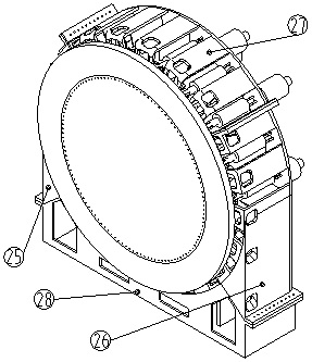
[0024] Embodiment 1: as figure 1 As shown, a main drive bearing test bench includes a bench 24, a power mechanism is integrated on the bench 24, and the power mechanism is used to provide axial force, radial force and overturning moment for the test bearing system. Test the bearing system, the test bearing system is connected with the power mechanism.
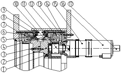
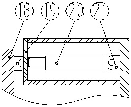
[0025] The test bearing system includes a test bearing 7, a test bearing connection flange 8, a test bearing load large flange 18 and a test bearing connection plate 3, and the test bearing connection flange 8 is connected to the test bearing outer ring and the test bearing load through high-strength bolts 9. The large flanges 18 are connected, the test bearing outer seal 6 is installed between the test bearing outer ring and the test bearing connection plate, the test bearing load large flange 18 is arranged on the outside of the bench 24, the test bearing load large flange 18 is connected with the power mechanism and The pow...
Embodiment 2
[0029] Embodiment 2: as figure 2 As shown, a main drive bearing test system includes a main drive bearing test bench, and the test bearing system and the power mechanism in the main drive bearing test bench 24 form a load test system, and the test bearing system and the driving mechanism are installed in the bench 24. system, the bearing system to be tested is connected to the drive system and the test bearing system and the bearing system to be tested rotate synchronously. The load test system, the bearing system to be tested and the drive system form the main drive bearing test system under simulated working conditions. Through two sets of bearing systems Synchronous operation, eliminating the friction of the rotating pair. By loading the test bearing system, the bearing force of the test bearing system is transmitted to the bearing system to be tested, thereby realizing the performance test of the bearing system to be tested, and simulating the real working conditions close...
PUM
 Abstract
Description
Claims
Application Information