
Desulfurization slurry density measuring device and method

A density measurement and desulfurization slurry technology, which is applied in the desulfurization field of power plants, can solve the problems of affecting the desulfurization effect, density measurement value deviation, high supersaturation of slurry, etc., to achieve automatic and convenient operation and maintenance, improve detection accuracy, and improve flushing cleanliness Effect

Pending Publication Date: 2021-03-26
邵加晓
View PDF0 Cites 1 Cited by
  • Summary
  • Abstract
  • Description
  • Claims
  • Application Information

AI Technical Summary

Problems solved by technology

The density value of the desulfurization slurry controls the discharge of gypsum slurry in the absorption tower to maintain the balance of materials in the absorption tower. If the density value is lower than a certain value, the slurry needs to be returned to the absorption tower for recycling. If the density value is higher than a certain value, If the density value of the desulfurized slurry is not detected accurately, it will be difficult to control the discharge of the desulfurized slurry, especially when the detected density value is low and the actual density value is high, the slurry may be supersaturated. Therefore, the detection accuracy of the density value of the desulfurization slurry seriously affects the desulfurization effect
[0003] There are many measurement methods for measuring the density value of desulfurization slurry in the desulfurization system of the power plant, but due to various reasons on site, the density measurement value is somewhat deviated, and there are also some problems in use and maintenance.

Method used


Image

  • Desulfurization slurry density measuring device and method

Examples


Embodiment Construction

[0016] The preferred embodiments of the present invention will be described in detail below in conjunction with the accompanying drawings, so that the advantages and features of the present invention can be more easily understood by those skilled in the art, so as to define the protection scope of the present invention more clearly.

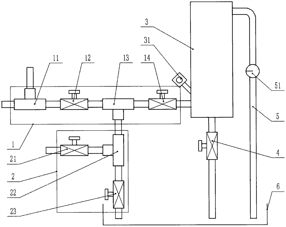
[0017] Such as figure 1 As shown, a desulfurization slurry density measuring device includes a slurry inlet pipeline 1, a water inlet and discharge pipeline 2, a measuring cylinder 3, a slurry discharge valve 4, an overflow pipe 5 and a slurry water collection tank 6, and the slurry inlet pipeline 1 is composed of the first slurry inlet pipe joint 11, the first slurry inlet valve 12, the second slurry inlet pipe joint 13 and the second slurry inlet valve 14 through connecting pipes, and the water inlet and discharge pipeline 2 is composed of the water inlet valve 21, the water inlet and outlet The slurry pipe joint 22 and the slurry discharge val...


PUM


Abstract

The present invention relates to a desulfurization slurry density measuring device and method. The device comprises a slurry inlet pipeline (1), a water inlet and slurry discharge pipeline (2), a measurement cylinder (3), a slurry discharge valve (4), an overflow pipe (5) and a slurry collection pool (6); the slurry inlet pipeline (1) is formed by sequentially connecting a slurry inlet pipe joint1 (11), a slurry inlet valve 1 (12), a slurry inlet pipe joint 2 (13) and a slurry inlet valve 2 (14); the water inlet and slurry discharge pipeline (2) is formed by connecting a water inlet valve (21), a water inlet and slurry discharge pipe joint (22) and a slurry discharge valve (23) through connecting pipes, a pressure transmitter (31) is arranged at the lower part of the measuring cylinder (3), a flowmeter (51) is arranged on the overflow pipe (5), and a slurry discharge valve (4) is arranged at the bottom of the measuring cylinder (3); the upper end of the overflow pipe (5) is connectedwith the upper part of the measuring cylinder (3), and the lower end is connected with the slurry collecting tank (6). The device is simple and novel in structure, high in detection accuracy and automatic and convenient to operate and maintain.

Description

technical field [0001] The invention relates to the technical field of desulfurization in power plants, in particular to a device and method for measuring the density of desulfurization slurry. Background technique [0002] The density value of the desulfurization slurry in the desulfurization system of the power plant is one of the important parameters to control the desulfurization effect. The desulfurization production process is the reaction process between the gypsum slurry and the sulfur dioxide in the flue gas in the desulfurization absorption tower. The desulfurization effect is controlled by controlling the density value of the gypsum slurry during the operation. The density value of the desulfurization slurry controls the discharge of gypsum slurry in the absorption tower to maintain the balance of materials in the absorption tower. If the density value is lower than a certain value, the slurry needs to be returned to the absorption tower for recycling. If the dens...

Claims


Application Information

Patent Timeline
Patent Type & Authority Applications(China)
IPC IPC(8): G01N9/04
CPCG01N9/04
Inventor 邵加晓何金磊兰金芳
Owner 邵加晓
Learn More