
Cylindrical wave amplitude characteristic mechanical compensation measurement system

A measurement system and cylindrical wave technology, applied in measurement devices, measuring electrical variables, instruments, etc., can solve the problems of reduced measurement accuracy, poor measurement accuracy, real-time detection deviation of cylinder wave amplitude, etc., to improve detection accuracy, The effect of avoiding bias

Pending Publication Date: 2021-03-26
BEIJING INST OF RADIO METROLOGY & MEASUREMENT
View PDF0 Cites 0 Cited by
  • Summary
  • Abstract
  • Description
  • Claims
  • Application Information

AI Technical Summary

Problems solved by technology

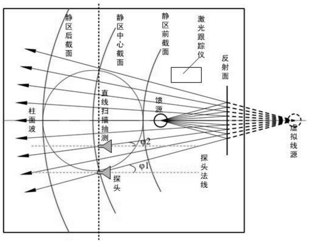
Since the cylindrical wave is generated by the virtual line source and presents a cylindrical divergence, when the amplitude characteristics of the center of the quiet zone are measured using a straight-line scanning guide rail, when the scanning position of the receiving probe antenna changes, the angle between the main lobe of the probe antenna and the virtual line source The angles ψ1 and ψ2 are constantly changing, which creates a deviation in the real-time detection of the cylinder wave amplitude, resulting in poor measurement accuracy and reduced measurement accuracy

Method used


Image

  • Cylindrical wave amplitude characteristic mechanical compensation measurement system
  • Cylindrical wave amplitude characteristic mechanical compensation measurement system
  • Cylindrical wave amplitude characteristic mechanical compensation measurement system

Examples


Embodiment Construction

[0021] In order to make the technical problems, technical solutions and beneficial effects to be solved by the present invention, the present invention will be described in further detail below with reference to the accompanying drawings and examples. It should be understood that the specific embodiments described herein are merely intended to illustrate the invention and are not intended to limit the invention.

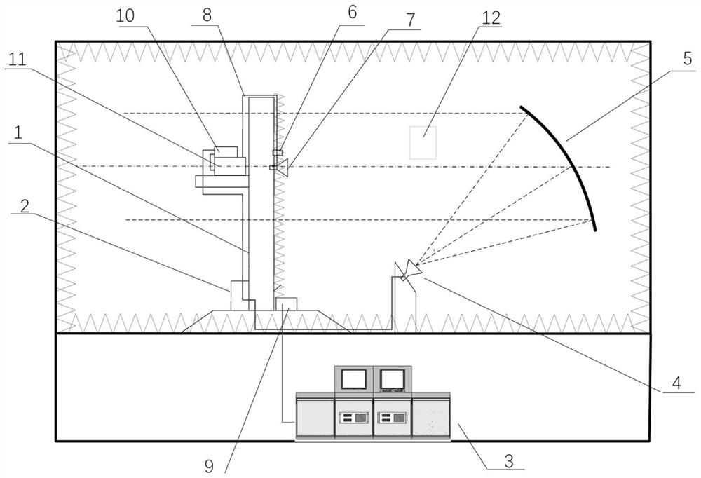
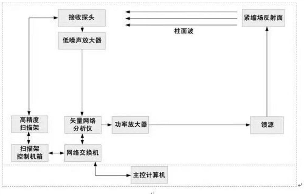
[0022] Refer Figure 1-2 The present invention provides a cylindrical wave amplitude characteristic mechanical compensation measuring system including an operating station 3, a scanning frame 1, and a stationary zone, a scanning frame 1 selected a large-scale pour T-type scanner, an operating station 3 loading There is a master, the stationary zone cylindrical field is composed of the cylindrical field reflecting surface 5 and the feed source 4, and the scanner is equipped with a power amplifier 10, a vector network analyzer 11, and a receiving probe 7 toward the column f...


PUM


Abstract

The invention discloses a cylindrical wave amplitude characteristic mechanical compensation measurement system which comprises an operation table, a scanning frame and a static area cylindrical field,a power amplifier, a vector network analyzer and a receiving probe are arranged on the scanning frame, and the receiving probe is arranged on a linear scanning device of the scanning frame through anorientation rotation holder. A laser tracker is installed in a reflection area between the scanning frame and a cylindrical surface field reflection surface, the receiving probe is connected with a vector network analyzer through a low-noise amplifier, the vector network analyzer is connected with the power amplifier, and the power amplifier is connected with a feed source through a control cabinet. The orientation rotation holder is arranged, the receiving probe is controlled to point to a virtual line source in real time, the laser tracker is arranged, the included angle relation between the scanning position of a receiving antenna of the probe and the virtual line source is measured in real time, corresponding angle amplitude compensation is conducted by controlling the orientation rotation holder, and therefore deviation generated by detection is avoided, and the detection precision is improved.

Description

Technical field [0001] The present invention relates to a cylindrical wave amplitude characteristic measuring system, and more particularly to a cylindrical wave amplitude characteristic mechanical compensation measurement system. Background technique [0002] With the development of stealth, anti-stealth technology and satellite technology, the accuracy and functional requirements of high performance radar antennas, antenna cover characteristics test and radar target RCS test are getting higher and higher. General test methods include far field testing, near-field testing, tightening field testing, etc., which is widely valued in terms of tightening field test applications, high testing accuracy, and convenient use. In recent years, a variety of types of tightening fields that adapted to different test needs have been built. The main types have a tightening field that produces planar waves and a tightening field that produces cylindrical waves, and there are differences in elect...

Claims


Application Information

Patent Timeline
Patent Type & Authority Applications(China)
IPC IPC(8): G01R29/10G01R35/00
CPCG01R29/10G01R35/005
Inventor 马永光吴翔何鑫杨金涛
Owner BEIJING INST OF RADIO METROLOGY & MEASUREMENT
Learn More