Rotary motor and rotor assembly thereof

A technology for rotating motors and rotors, which is applied in the direction of electric components, electrical components, magnetic circuit rotating parts, etc., which can solve problems such as limiting the performance of motors, and achieve the effect of enhancing reluctance torque

Active Publication Date: 2021-03-26
北京和山逢泰科技有限公司
View PDF30 Cites 1 Cited by
  • Summary
  • Abstract
  • Description
  • Claims
  • Application Information

AI Technical Summary

Problems solved by technology

Therefore, it is easy to produce magnetic saturation and limit the performance of the motor

Method used


Image

  • Rotary motor and rotor assembly thereof
  • Rotary motor and rotor assembly thereof
  • Rotary motor and rotor assembly thereof

Examples


no. 1 example

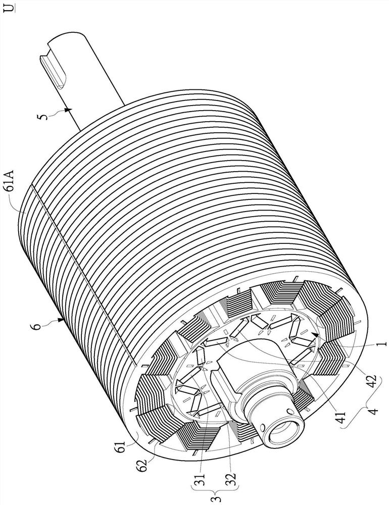
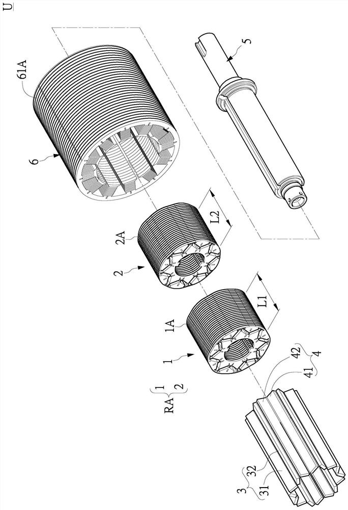
[0037] First, see figure 1 and figure 2 as shown, figure 1 It is a three-dimensional combined schematic view of the rotating electrical machine in the first embodiment of the present invention, figure 2 It is a three-dimensional exploded schematic view of the rotating electrical machine according to the first embodiment of the present invention. The present invention provides a rotating electric machine U and its rotor assembly RA, that is, an electric motor and a rotor applied to the electric motor. The rotary electric machine U may include a rotating shaft 5 , a rotor assembly RA, a first magnetic element set 3 , a second magnetic element set 4 and a stator assembly 6 . The rotor assembly RA can be arranged on the rotating shaft 5, the first magnetic element group 3 and the second magnetic element group 4 can be arranged on the rotor assembly RA, and the stator assembly 6 can be arranged corresponding to the rotor assembly RA, so that the rotor assembly RA can be relati...

no. 2 example

[0061] First, see Figure 10 and Figure 11 as shown, Figure 10 It is a three-dimensional combined schematic view of the rotating electrical machine according to the second embodiment of the present invention, Figure 11 It is a three-dimensional exploded schematic view of the rotating electrical machine according to the second embodiment of the present invention. Depend on Figure 10 and Figure 11 and figure 1 and figure 2 It can be seen from the comparison that the biggest difference between the second embodiment and the first embodiment is that the rotating electrical machine U provided by the second embodiment can be provided with two second rotors 2 .

[0062] Then, the first predetermined length L1 of the first rotor 1 and the second predetermined length L2 of the two second rotors 2 and the distance between the first rotor 1 and the second rotor 2 can be adjusted according to the application occasion of the rotating electrical machine U. Relative position, in ...

no. 3 example

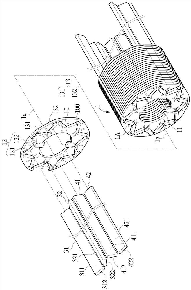
[0065] First, see Figure 12 to Figure 14 as shown, Figure 12 is a schematic perspective view of the first rotor of the rotor assembly of the third embodiment of the present invention, Figure 13 is a schematic front view of the first rotor of the rotor assembly of the third embodiment of the present invention, Figure 14 for Figure 13 An enlarged schematic of part XIV. Depend on Figure 12 and Figure 13 and Figure 3 to Figure 6 It can be seen from the comparison that the salient poles of the first rotor 1 provided by the third embodiment can be arranged on the first quadrature axis Q1 , the first direct axis D1 and the second direct axis D2 at the same time.

[0066] Based on the above, further speaking, the plurality of first segments 1001 , the plurality of second segments 1002 and the plurality of third segments 1003 may be protruding relative to the first rotor body 10 . In this way, a gentle section 1004 that is gently arranged relative to the adjacent first s...


PUM


Abstract

The invention discloses a rotary motor and a rotor assembly thereof. The rotor assembly comprises a first rotor. The first rotor comprises a first central shaft, a first rotor body, a first shaft hole, a plurality of first through hole groups, a plurality of second through hole groups and a first outer edge. The plurality of first through hole groups surround the first central shaft and are arranged at intervals. The plurality of second through hole groups surround the first central shaft and are arranged at intervals. One second perforation group is arranged between two adjacent first perforation groups. A first quadrature axis is defined between the adjacent first through hole group and second through hole group. The first through hole group defines a first straight axis, and the secondthrough hole group defines a second straight axis. The first outer edge includes a plurality of first sections respectively corresponding to a first quadrature axis, a plurality of second sections respectively corresponding to a first straight axis, and a plurality of third sections respectively corresponding to a second straight axis. The plurality of first sections are arranged in a protruding manner relative to the first rotor body. Therefore, the effect of enhancing the reluctance torque is achieved.

Description

technical field [0001] The invention relates to an electrical machine, in particular to a rotating electrical machine and a rotor assembly thereof. Background technique [0002] First of all, in the prior art, under the operation of the motor at high speed and / or high torque, the operation of leading the phase current will be carried out. This operation will make the magnetic force of the rotor push to the next tooth structure on the stator to generate a magnetic resistance torque. [0003] However, in this case, the magnetic flux density is particularly high at the quadrature axis (Q axis) of the magnet because the magnetic force is squeezed and compressed to the next tooth structure on the stator. Therefore, the phenomenon of magnetic saturation is easy to occur, which limits the performance of the motor. [0004] Therefore, in view of this, how to overcome the above-mentioned defects through the improvement of structural design has become one of the important issues tha...

Claims


Application Information

Patent Timeline
Patent Type & Authority Applications(China)
IPC IPC(8): H02K1/27H02K1/28
CPCH02K1/276H02K1/28
Inventor 林继谦萧家祥阎柏均
Owner 北京和山逢泰科技有限公司
Why Eureka
Try Eureka