Cable sealing device for permanent magnet synchronous motor

A permanent magnet synchronous motor and cable sealing technology, which is applied to the cable entrance sealing device, electromechanical device, cooling bus device, etc., can solve the problems of hidden dangers in insulation, unresolved sealing, and poor sealing performance, and achieve simple connection Convenient, simple and convenient assembly, good sealing effect

Pending Publication Date: 2021-03-26
WUHAN HENGXINTAI OIL EQUIP MFG CO LTD
View PDF4 Cites 3 Cited by
  • Summary
  • Abstract
  • Description
  • Claims
  • Application Information

AI Technical Summary

Problems solved by technology

[0006] During the research and development process of the applicant's small-diameter and small-size oil-submersible permanent-magnet synchronous motor, the oil-submersible permanent-magnet permanent-magnet synchronous motor with an outer diameter of 66mm is not specifically designed for this type of small-diameter submersible in the prior art. The sealing structure at the outlet of the motor, such as the above-mentioned Chinese patent with the authorized announcement number CN105186439B, is too complicated, and there are parts such as springs, which cannot be assembled and applied to small-diameter submersible motors
The above-mentioned authorized notification number is the Chinese patent of CN206962616U, which has the following problems: one is that the outlet cable of the submersible motor is generally three wires, not one, and the insulation between the three wires will exist when it is placed in the middle position during sealing. hidden danger; the second is that the sealing performance of the gap between the outer wall of the cable lead-out line and the inner wall of the press-fit nut is still not resolved, and the sealing performance is not good

Method used


Image

  • Cable sealing device for permanent magnet synchronous motor
  • Cable sealing device for permanent magnet synchronous motor

Examples


Embodiment

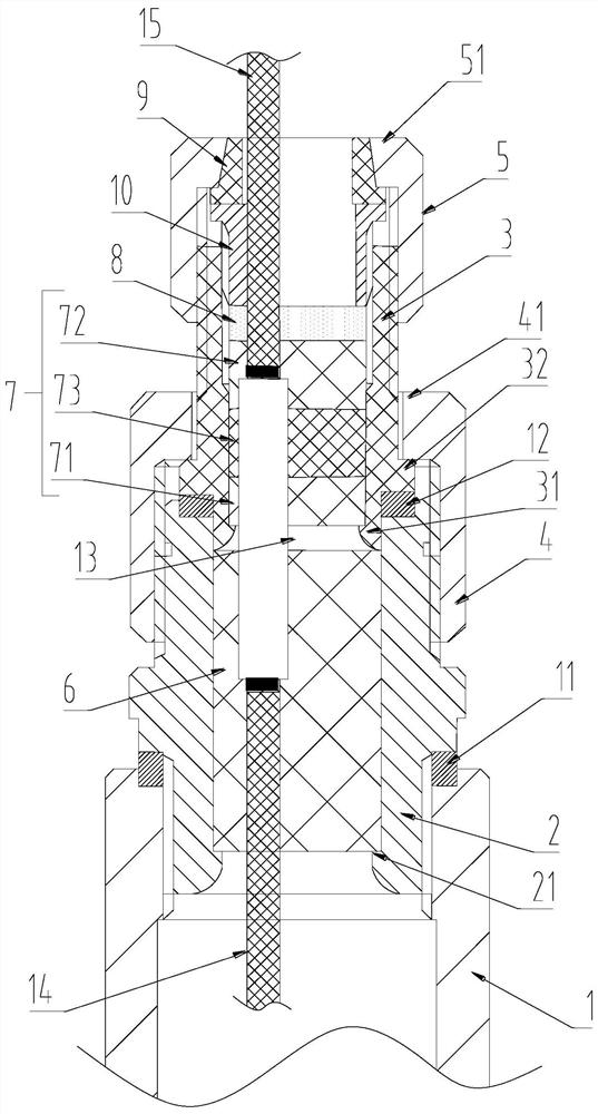
[0036] EXAMPLES: One permanent magnet synchronous motor cable sealing device, such as figure 1 As shown, including the motor outgoing seat 1, three motor outlet cable 14, three upper cable 15, the hollow first sealing joint 2, the sealing cushion in the first sealing joint 2 is connected to the first sealing joint 2 The first block 4 of the outer wall, the hollow second sealing joint 3, is located in the seal 7 in the second sealing joint 3, and the thread is threaded connected to the head 10 of the inner wall of the second sealing joint 3, and the thread is connected to the second seal. The second compression cover 5 of the joint 3.

[0037] Such as figure 1 As shown, the first sealing joint 2 is threaded with the motor outgoing line 1, and the first sealing joint 2 is provided with a first sealing pad 11 between the motor outgoing lines 1, and the first sealing pad 11 is a metal pad. The first sealing joint 2 is formed in the inner step one 21, and one end of the sealing cushi...


PUM


Abstract

The invention relates to the technical field of oil extraction equipment, and discloses a cable sealing device for a permanent magnet synchronous motor. The device comprises a motor wire out seat. Thedevice is characterized by further comprising a hollow first sealing joint, a first sealing cushion located in the first sealing joint, a first gland connected to the outer wall of the first sealingjoint in a threaded mode, a hollow second sealing joint, a sealing piece located in the second sealing joint, and a pressing head which is in threaded connection with the interior of the second sealing joint and abuts against the sealing piece. The sealing device has the following advantages and effects that the sealing problem between the outgoing cable of the permanent magnet synchronous motor and the motor is solved by arranging the multi-layer sealing structure, the sealing is reliable, and meanwhile high temperature resistance, high pressure resistance and corrosion resistance are achieved; the motor outgoing cable is convenient to butt with an external cable, the wiring position is firm and reliable, the use performance of the motor is greatly enhanced, and the service life of the motor is prolonged.

Description

Technical field [0001] The present invention relates to the technical field of oil production equipment, and in particular, a cable sealing device for a permanent magnet synchronous motor. Background technique [0002] The dubwide direct drive permanent magnet synchronous motor is the power source of the sub-oil screw pump system, which requires a few kilometers deep under the oil well, which is affected by the downhole pressure, temperature, and corrosive problems, the sealing problem of motor extension cable It is particularly serious. [0003] In the prior art, the authorized bulletin is disclosed in China Patent Publication CN2817188Y discloses an integrated sub-oil motor with a sealing device, and the public official is disclosed in China Patent Publication No. CN201142608Y. It is a sealing structure for the sub-oil motor itself and does not involve sealing at the outline cable. [0004] The authorized bulletin is disclosed in Chinese patents for CN105186439B discloses a cab...

Claims


Application Information

Patent Timeline
Patent Type & Authority Applications(China)
IPC IPC(8): H02K5/22H02G15/013H02G5/10
CPCH02G15/013H02K5/10H02K5/225
Inventor 胡冰苏传骥赵根东刘明祥
Owner WUHAN HENGXINTAI OIL EQUIP MFG CO LTD
Why Eureka
Try Eureka