Light-emitting housing

A technology for shells and light-emitting elements, which is applied in the direction of light sources, semiconductor devices of light-emitting elements, electrical equipment shells/cabinets/drawers, etc., to achieve the effect of avoiding drilling steps

Inactive Publication Date: 2021-03-26
PEGATRON
View PDF8 Cites 0 Cited by
  • Summary
  • Abstract
  • Description
  • Claims
  • Application Information

AI Technical Summary

Problems solved by technology

The shell has an outer surface and an inner surface

Method used


Image

  • Light-emitting housing
  • Light-emitting housing
  • Light-emitting housing

Examples


Embodiment Construction

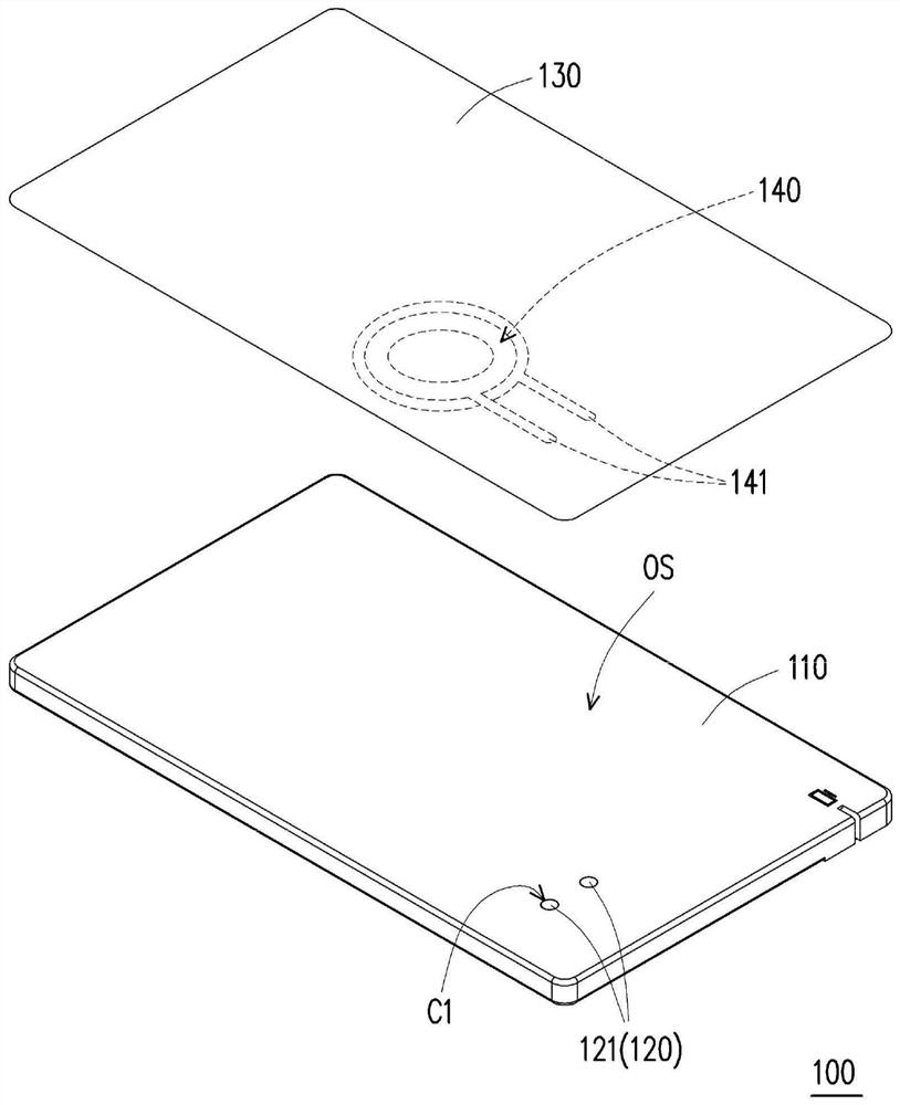
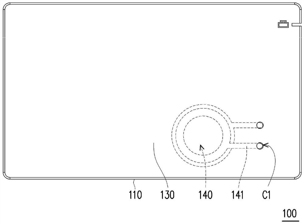
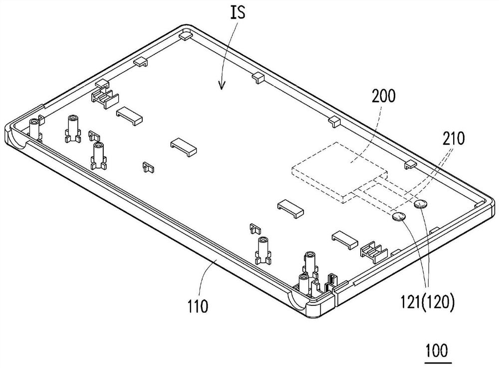
[0048] Figure 1A It is a three-dimensional exploded schematic diagram of some components of the luminous housing according to an embodiment of the present invention. Figure 1B for Figure 1A A schematic top plan view of the light-emitting element attached to the housing. Figure 1C for Figure 1A A three-dimensional schematic view of the illuminated housing in the other direction. Figure 2A for Figure 1A A schematic plan view of the separated state of the conductive structure and the shell. Figure 2B for Figure 2A A schematic plan view of the mating state of the conductive structure and the housing.

[0049] Please refer to Figure 1A to Figure 1C , the light-emitting housing 100 of the present invention is, for example, applied to the housing structures of notebook computers, tablet computers, mobile phones, household appliances, projectors, or other similar electronic devices, and the light-emitting housing 100 is provided with a light-emitting element. When a curre...


PUM


Abstract

A light-emitting housing including a housing body, a conductive structure, and a light-emitting element is provided. The housing body has an outer surface and an inner surface. The conductive structure is embedded in the housing body and penetrates the outer surface and the inner surface. A decorative film is attached to the outer surface of the housing body. The light-emitting element is disposedon the outer surface of the housing body. The light-emitting element has two wires coupled to the conductive structure. The electric structure is adapted to transmit a current to the two wires, so that the light-emitting element emits light.

Description

technical field [0001] The invention relates to a casing, in particular to a luminous casing with decoration and lighting functions. Background technique [0002] The light-emitting shell of the prior art mainly forms holes corresponding to the light-emitting area on the product shell by drilling holes for the internal light source to emit. When the electronic product is in operation, the light from the internal light source can be transmitted from the hole in the product shell to the human eye to provide vision. Effect. In addition, drilling holes will also reduce the strength of the product shell, so a shell with a certain thickness is required, which is not conducive to meeting the light and thin requirements of the product. Contents of the invention [0003] The invention provides a luminous shell, which can generate light when the current passes through, so as to have decorative effect and visual effect, and can avoid extensive drilling steps to reduce manufacturing ...

Claims


Application Information

Patent Timeline
Patent Type & Authority Applications(China)
IPC IPC(8): H05K5/02H04M1/02G06F1/16
CPCH05K5/0243H05K5/0247H04M1/0283G06F1/1613H01L33/62F21Y2115/20F21V33/0004F21V3/04
Inventor 邱榆皓杨字民
Owner PEGATRON
Why Eureka
Try Eureka