Down filling machine
A down filling machine and case technology, which is applied in the field of down filling machines, can solve the problems of unsatisfactory dispersing effect and inability to disperse down, so as to achieve ideal dispersing effect and improve bulkiness
- Summary
- Abstract
- Description
- Claims
- Application Information
AI Technical Summary
Problems solved by technology
Method used
Image

Examples
specific Embodiment approach 1
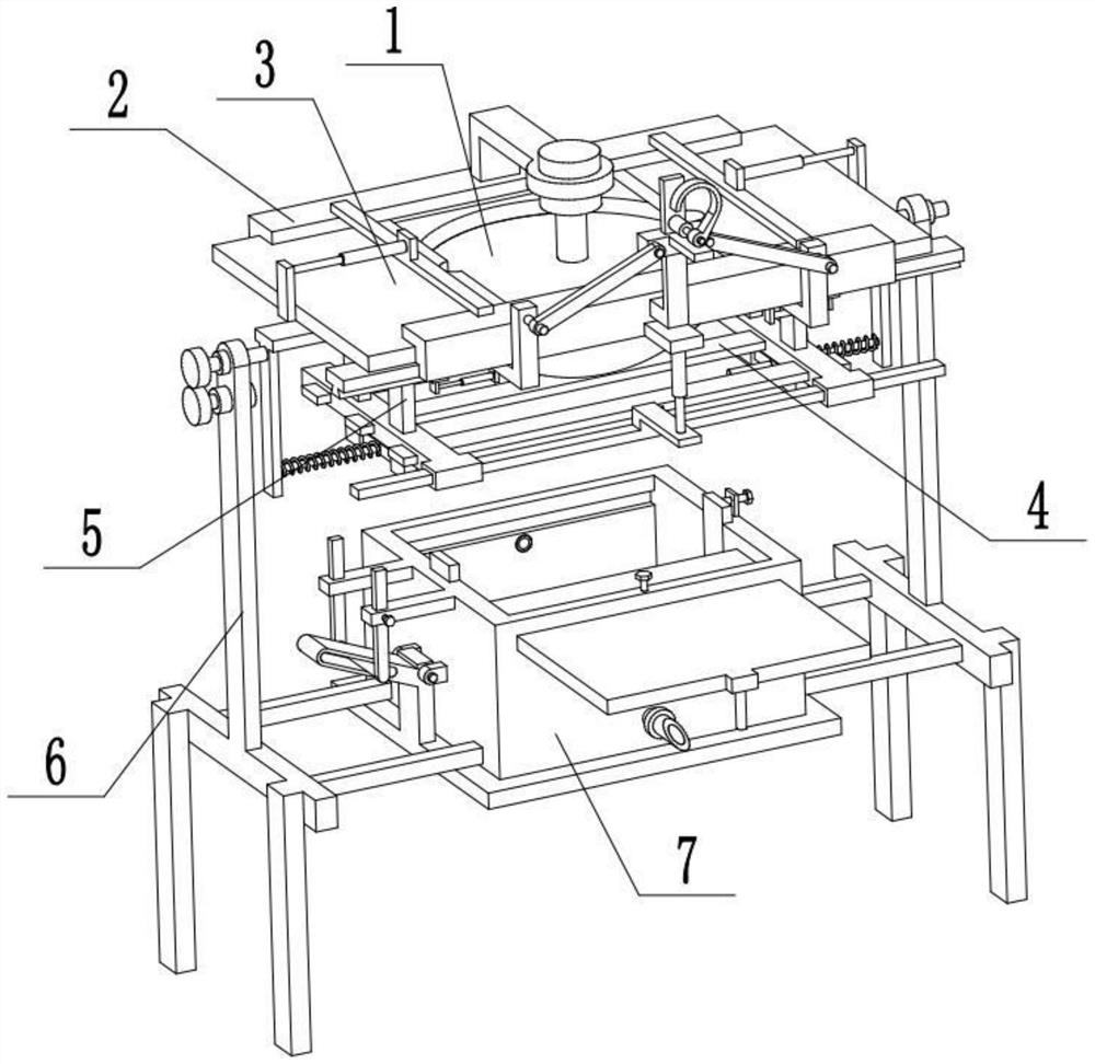
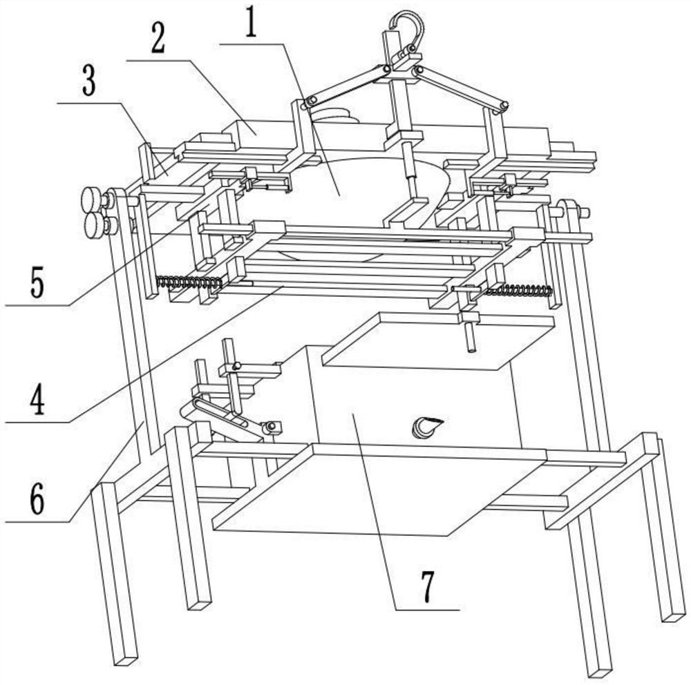
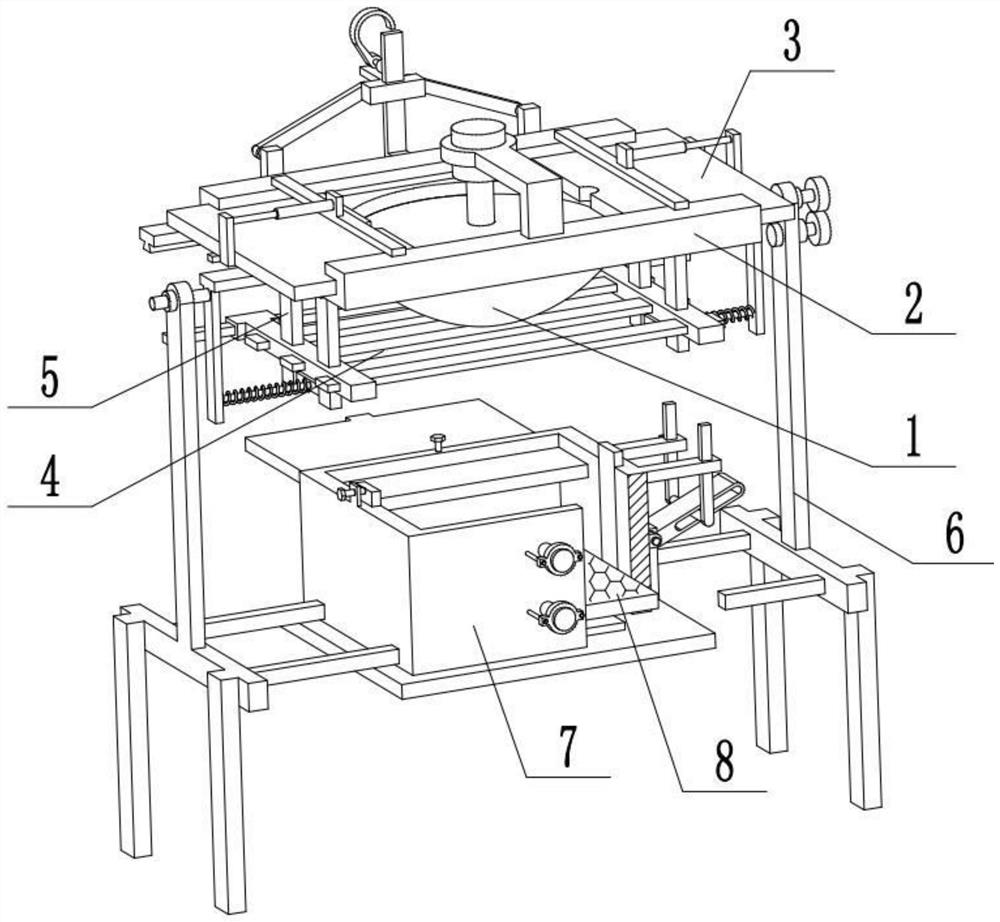
[0032] Combine below Figure 1-11 Describe this embodiment, a kind of down filling machine, including liner cloth 1, top frame 2, first air pump 2-1, first electric push rod 2-3, cover plate 3, elastic cord 4 and side plate 4-1, The central portion of the top frame 2 is hollowed out, the gall cloth 1 is fixedly connected and communicated with the central portion of the top frame 2, the middle part of the top frame 2 is fixedly connected to the first air pump 2-1, and the top frame 2 is symmetrically fixedly connected to two second air pumps. An electric push rod 2-3, the output ends of the two first electric push rods 2-3 are respectively fixedly connected to a cover plate 3, and the two cover plates 3 are symmetrically and flexibly connected to the top frame 2; the bottom surface of the top frame 2 is arranged symmetrically There are two side plates 4-1, and a plurality of elastic cords 4 are fixedly connected between the two side plates 4-1. When in use, control the extensi...
specific Embodiment approach 2
[0034] Combine below Figure 1-11 To illustrate this embodiment, the outlet pipe 2-2, the output end of the first air pump 2-1 is fixedly connected to the outlet pipe 2-2, and the inner end surfaces of the two cover plates 3 are respectively provided with a groove; the groove The diameter is equal to the diameter of the outlet pipe 2-2. The lower end of the air outlet pipe 2-2 goes deep into the gall cloth 1, and the gas is output from the air outlet pipe 2-2. When the two cover plates 3 are closed, the air outlet pipe 2-2 is located in the two grooves to prevent the two cover plates 3 from closing Leaks appear at the end to further prevent the down from running out of the gap when the down is blown.
specific Embodiment approach 3
[0036]Combine below Figure 1-11 Describe this embodiment, the second electric push rod 2-4 and the cross bar 2-5, the second electric push rod 2-4 is fixedly connected to the front end of the top frame 2, the output of the second electric push rod 2-4 The ends are fixedly connected to the cross bar 2-5, and the two side plates 4-1 are respectively slidably connected to the two ends of the cross bar 2-5. The second electric push rod 2-4 starts to drive the cross bar 2-5 to move up and down, and the cross bar 2-5 drives two side plates 4-1 and a plurality of elastic cords 4 to move up and down, changing the distance between the elastic cord 4 and the top frame 2. The spacing between the elastic cords 4 can change the impact strength of the down in the lining cloth 1. When the amount of down in the lining cloth 1 is large, the down can also be scattered well.
PUM
 Abstract
Description
Claims
Application Information
 - R&D Engineer
- R&D Manager
- IP Professional
- Industry Leading Data Capabilities
- Powerful AI technology
- Patent DNA Extraction
Browse by: Latest US Patents, China's latest patents, Technical Efficacy Thesaurus, Application Domain, Technology Topic.
© 2024 PatSnap. All rights reserved.Legal|Privacy policy|Modern Slavery Act Transparency Statement|Sitemap