Sharps storage box with automatic cutting function
An automatic cutting and storage box technology, which is applied in the field of storage tool boxes in the field of medical care, can solve the problems of limited width, inconvenient use, and heavy strength, and achieve the effect of avoiding cutting difficulties, wide practicability, and fast storage
- Summary
- Abstract
- Description
- Claims
- Application Information
AI Technical Summary
Problems solved by technology
Method used
Image
Examples
Embodiment 1
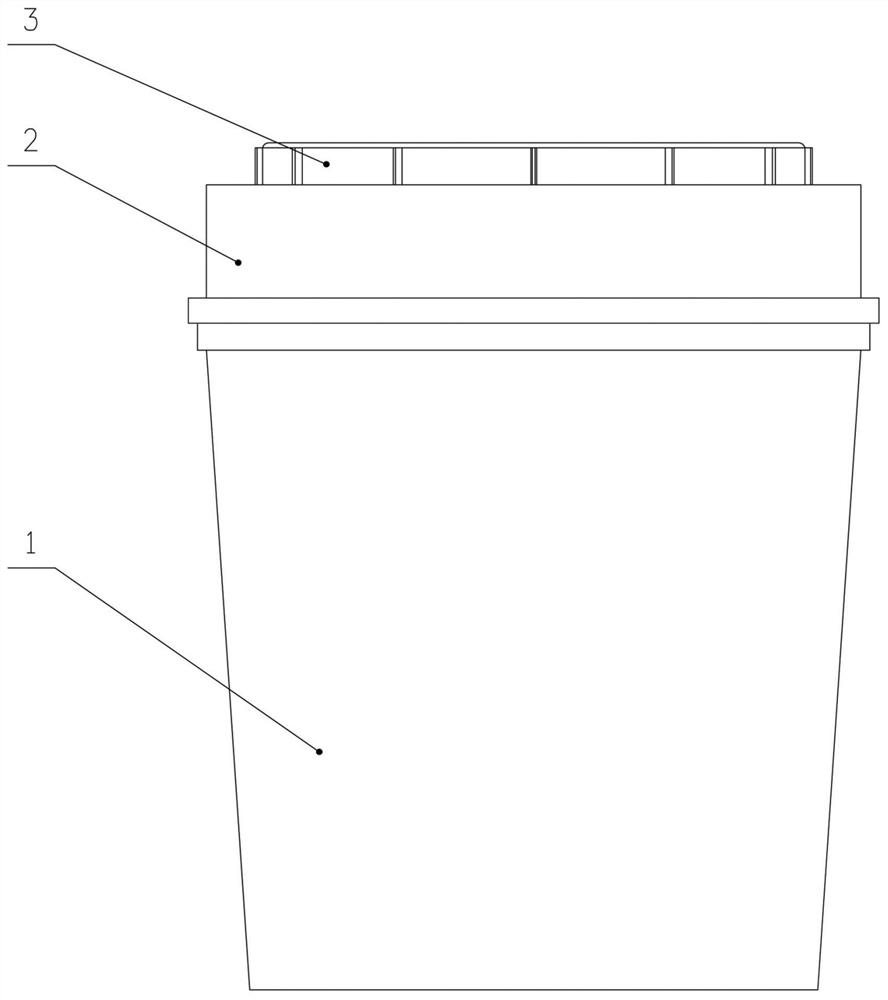
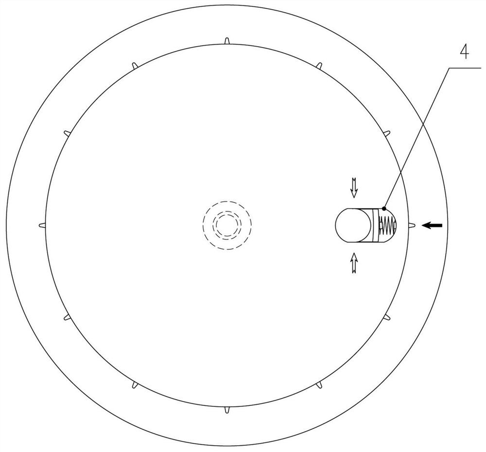
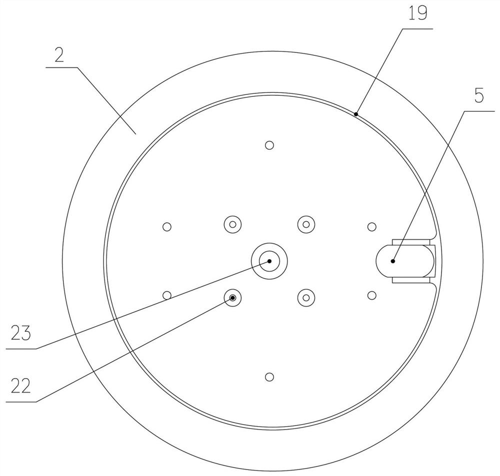
[0029] Embodiment 1: adopt a kind of as figure 1 In the sharps storage box shown, the spiral cutter installed can automatically cut the needle part according to the operation. The appearance of the storage box is as follows: figure 1 and figure 2 shown. It can be seen from the figure that its main part includes a cup body 1 for accommodating sharp tools, a main cover 2 fixedly set on the upper part of the cup body 1, and a secondary cover 3 set on the outside of the main cover 2 that can rotate but cannot be separated. The function is equivalent to the existing storage box. But in this example, from figure 2 and image 3 It can be seen from the figure that the main cover 2 and the auxiliary cover 3 are respectively provided with flat perforations, that is, the flat hole 4 of the auxiliary cover and the flat hole 5 of the main cover.
[0030] Specifically, after the secondary cover 3 is removed from the main cover 2, the image 3 It can be seen that the main cover 2 inc...
Embodiment 2
[0036] Embodiment 2: On the basis of Embodiment 1, the flat holes 5 of the main cover can be distributed not only along the radial direction, but also along the tangential or approximately tangential direction to the spiral saw blade. When the spiral baffle rotates, it can Press the needle seat and the elastic pressing part to slide properly in the flat hole 5 of the main cover.
Embodiment 3
[0037] Embodiment 3: On the basis of Embodiment 1, the elastic pressing part 6 adopts such as Figure 11 In the shown structural form, a push-pull rod 24 is connected to the rear side of the elastic pressing part 6. The push-pull rod 24 penetrates outside the annular wall 19 of the main cover and is connected with a handle 21. By pulling the handle outward After 21, the position of the elastic pressing member 6 located in the side groove can be changed, thereby changing the gap of the insertion hole. This solution is suitable for man-made control of the insertion depth of the needle. For example, after the entire needle holder is fully inserted into the storage box, the handle 21 is released, so that the elastic pressing part 6 clamps the needle connecting tube part, and then triggers the pressure contact switch 18 to start the motor rotation.
PUM
 Abstract
Description
Claims
Application Information
 - R&D
- Intellectual Property
- Life Sciences
- Materials
- Tech Scout
- Unparalleled Data Quality
- Higher Quality Content
- 60% Fewer Hallucinations
Browse by: Latest US Patents, China's latest patents, Technical Efficacy Thesaurus, Application Domain, Technology Topic, Popular Technical Reports.
© 2025 PatSnap. All rights reserved.Legal|Privacy policy|Modern Slavery Act Transparency Statement|Sitemap|About US| Contact US: help@patsnap.com


