Incense stick dyeing device for incense stick processing
A fragrance-dyeing and hygienic technology, which is applied in the direction of gasification substances, can solve the problems of cumbersome operation process, labor-intensive, and low work efficiency, and achieve the effects of simple operation, improved work efficiency, and labor-saving
- Summary
- Abstract
- Description
- Claims
- Application Information
AI Technical Summary
Problems solved by technology
Method used
Image

Examples
Embodiment 1
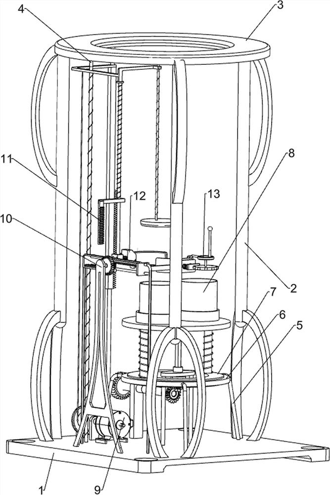
[0031] A device for dyeing incense feet for hygienic incense processing, such as Figure 1 to Figure 4 As shown, it includes a base 1, a first support frame 2, a top plate 3, a first guide rod 4, a first support rod 5, a first turntable 6 and a first circular rail 7, and the top of the base 1 is connected with three A first support frame 2, a top plate 3 is connected between the tops of the three first support frames 2, a first guide rod 4 is connected between the rear side of the top of the base 1 and the bottom of the top plate 3, and the top of the base 1 is evenly spaced along the circumferential direction. There are three first support rods 5, the first turntable 6 is connected between the three first support rods 5, and the first round rail 7 is connected to the first turntable 6 in a rotating manner, and also includes a pressing component 8 and a flattening mechanism 9 and a clamping mechanism 10 , a pressing assembly 8 is provided on the first circular rail 7 , a flatt...
Embodiment 2
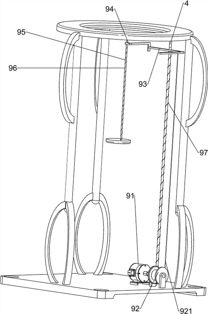
[0038] On the basis of Example 1, such as Figure 5 As shown, a rotating mechanism 11 is also included, and the rotating mechanism 11 includes a fourth guide rod 111, a second rack 112, a second support rod 113, a rotating rod 114, a one-way gear 115, a bevel gear transmission assembly 116, a third Support rod 117, support plate 118, inner diamond sleeve 119 and rhombus rod 1110, the fourth guide rod 111 is connected between the top of the base 1 and the bottom of the top plate 3, the first connecting rod 93 is slidingly matched with the fourth guide rod 111, the second The second rack 112 is slidingly connected to the four guide rods 111, the second rack 112 is connected to the first connecting rod 93, the rear side of the top of the base 1 is connected to the second support rod 113, and the second support rod 113 is connected in a rotational manner. There is a rotating rod 114, a one-way gear 115 is connected to the rotating rod 114, the second rack 112 will mesh with the on...
Embodiment 3
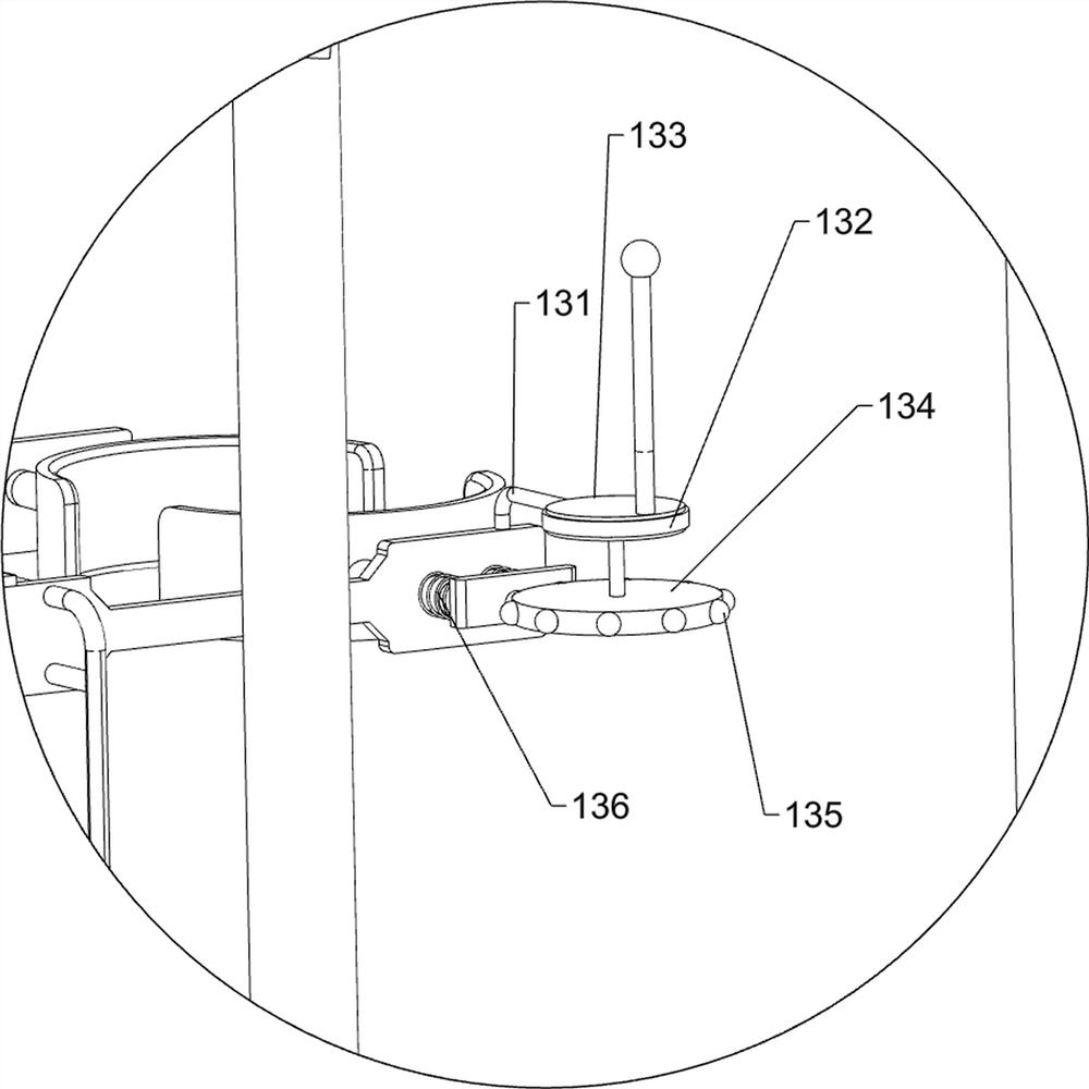
[0041] On the basis of Example 2, such as Figure 6 As shown, it also includes a depressing mechanism 12, the depressing mechanism 12 includes a connecting block 121, a fifth spring 122 and an oblique block 123, the bottom of the second guide rod 101 is connected with the connecting block 121, and the connecting block 121 is slidably connected There is an oblique block 123 , a fifth spring 122 is connected between the oblique block 123 and the connection block 121 , and the oblique block 123 cooperates with the second turntable 82 .
[0042] The second guide rod 101 drives the connecting block 121 to move downward when moving downward, and the connecting block 121 moves downward to drive all the devices on it to move downward together. When the oblique block 123 moves to contact with the second rotating disk 82, the second The three connecting rods 103 are also resisted by the third guide rod 109. At this moment, the oblique block 123 continues to move downwards and presses th...
PUM
 Abstract
Description
Claims
Application Information
 - R&D Engineer
- R&D Manager
- IP Professional
- Industry Leading Data Capabilities
- Powerful AI technology
- Patent DNA Extraction
Browse by: Latest US Patents, China's latest patents, Technical Efficacy Thesaurus, Application Domain, Technology Topic.
© 2024 PatSnap. All rights reserved.Legal|Privacy policy|Modern Slavery Act Transparency Statement|Sitemap