Die through hole device and machining method thereof

A mold and stable technology, used in metal processing equipment, perforation tools, manufacturing tools, etc., can solve the problems of reducing production efficiency, flattening of inserts, affecting the accuracy of through holes, etc., to improve fixing efficiency, ensure stability, improve The effect of movement stability

Inactive Publication Date: 2021-03-30
钟锋良
View PDF7 Cites 2 Cited by
  • Summary
  • Abstract
  • Description
  • Claims
  • Application Information

AI Technical Summary

Problems solved by technology

Penetration molding relies on mold clamping to make the molding insert collide with a certain plane of the opposite mold core and achieve a tight fit. If the mold clamping is not in place or mold expansion occurs during the production process, the orifice will have closed flashes. The hole cannot be penetrated, and the flash needs to be removed by trimming die or manually in the later stage, which may easily cause problems such as size out-of-tolerance, missed deburring, etc.
If the length of the forming part of the molding insert is greater than the theoretical length, the insert will hit the mold surface first when the mold is closed, and the molding insert will be compressed. After multiple productions, the insert will be flattened, resulting in a size out of tolerance. At this time, inserts must be replaced, which reduces production efficiency and increases cost input
[0003] Excessive punching is used for the through hole of the existing mold. Excessive punching pressure will easily cause damage to the mold and affect the precision of the through hole. Therefore, further improvement is required.

Method used


Image

  • Die through hole device and machining method thereof
  • Die through hole device and machining method thereof
  • Die through hole device and machining method thereof

Examples


Embodiment Construction

[0029] Next, the technical solutions in the embodiments of the present invention will be apparent from the embodiment of the present invention, and it is clearly described, and it is understood that the described embodiments are merely embodiments of the present invention, not all of the embodiments. Based on the embodiments of the present invention, there are all other embodiments obtained without making creative labor without making creative labor premises.

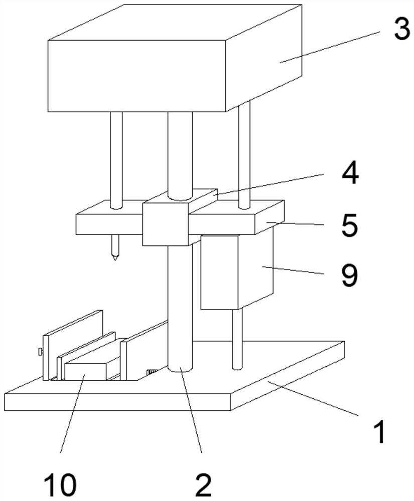
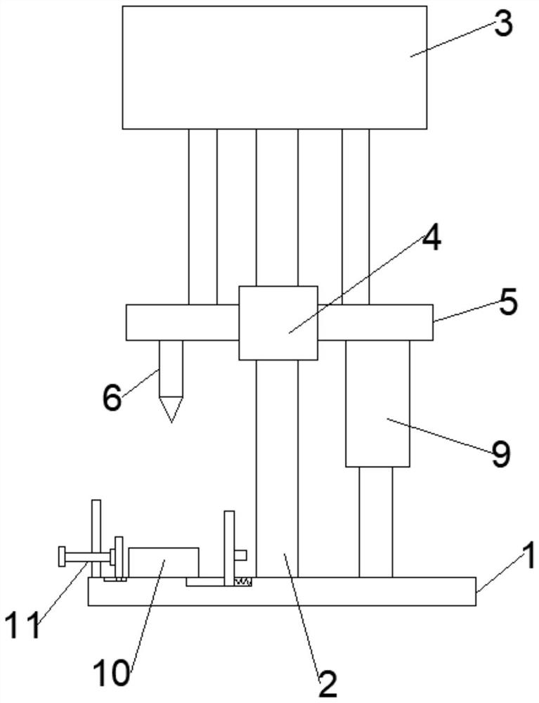
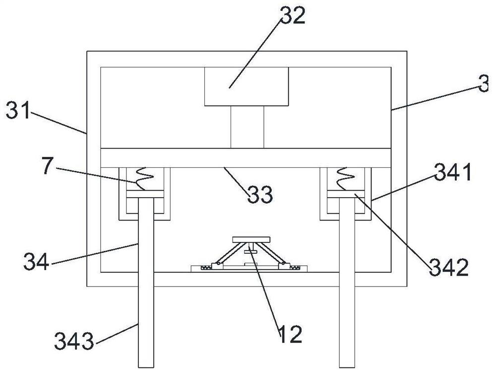
[0030] See Figure 1-7 In the embodiment of the present invention, a mold via apparatus includes a machining base 1, and the upper portion of the processing base 1 is mounted with a fixed vertical column 2, and a stamper 3 is attached to the top end of the fixed vertical column 2, and the fixed vertical column 2 The upper casing is provided with a stable sleeve 4. There is a punching block 5 on both sides of the stable sleeve 4, and the lower portion of the punching block 5 is provided with a stamping head 6 and a stabilizer...


PUM


Abstract

The invention relates to the technical field of die through holes, and provides a die through hole device. The device comprises a machining base, wherein a fixed vertical column is installed on the upper portion of the machining base, a stamping device is installed at the top end of the fixed vertical column, the fixed vertical column is sleeved with a stable sleeve block, stamping blocks are arranged on the two sides of the stable sleeve block, and a stamping head and a stabilizer are arranged on the lower portions of the stamping blocks. The stabilizer and the machining base are connected and installed, a die is placed on the upper portion of the machining base, and fixators are arranged on the two sides of the die. According to the die, the moving stability of positioning blocks is improved, the position of one side of the die can be positioned through the positioning blocks, different positions of the die can be punched conveniently, clamping springs can drive clamping rods to extrude the die, the die fixing effect is achieved, meanwhile, the die can be fixed at different positions, and the fixing efficiency of the die is improved.

Description

Technical field [0001] The present invention relates to the field of mold through holes, and more particularly to a mold through hole device and a processing method thereof. Background technique [0002] Mold, industrial production with various shapes and characteristics of desired products for injection molding, blow molding, extrusion, die casting or forging molding, smelting, stamping, etc. Briefly, the mold is a tool for fabricating a molded article, which consists of various parts, and different molds are composed of different parts. It is mainly processed by the physical state of the physical state of the forming material; two of the mold through hole forming structures: Turning through the formation, insert molding. Turning the molding relying on the mold to shape the molded insert to touch the opposite core, it is closely fit, if the mold is not in place or the expansion mode during the production process, the aperture will have a closed flying edge, The holes cannot be p...

Claims


Application Information

Patent Timeline
Patent Type & Authority Applications(China)
IPC IPC(8): B21D28/04B21D28/34B21D55/00F16F15/067
CPCB21D28/04B21D28/34B21D55/00F16F15/067
Inventor 钟锋良陈萌
Owner 钟锋良
Why Eureka
Try Eureka