Rapid slag ladling device for molten steel in steel ladle

A molten steel, rapid technology, applied in the direction of mechanical cleaning, manufacturing tools, metal processing equipment, etc., can solve the problems of large ladle volume, potential safety hazards, long operation time, etc., to achieve simple equipment structure design, improve cleaning efficiency, and use effect obvious effect

Inactive Publication Date: 2021-03-30
湖北楠田工模具科技有限公司
View PDF8 Cites 0 Cited by
  • Summary
  • Abstract
  • Description
  • Claims
  • Application Information

AI Technical Summary

Problems solved by technology

[0002] In the iron and steel smelting industry, the molten steel is usually transferred through the ladle. The molten steel usually cleans the scum on the upper layer of the molten steel in the ladle. At present, many smelting factories use cranes to lift the ladle and tilt it at a certain angle. After being placed on an incline, the scum and impurities with low density on the upper layer of molten steel will flow down to achieve the purpose of slag removal. Due to the large size and weight of the ladle and the high temperature of molten steel, this operation method has great potential safety hazards , the operation time is relatively long, and the slag removal is not thorough enough, and even a certain amount of molten steel will be poured out when dumping, resulting in waste. The above-mentioned drawbacks have not been well resolved in many iron and steel smelting factories

Method used


Image

  • Rapid slag ladling device for molten steel in steel ladle
  • Rapid slag ladling device for molten steel in steel ladle
  • Rapid slag ladling device for molten steel in steel ladle

Examples


Embodiment Construction

[0013] The technical solutions of the present invention will be clearly and completely described below in conjunction with the accompanying drawings of the present invention. Obviously, the described embodiments are only some of the embodiments of the present invention, not all of them. Based on the embodiments of the present invention, all other embodiments obtained by persons of ordinary skill in the art without making creative efforts belong to the protection scope of the present invention.

[0014] In the description of the present invention, it should be noted that the terms "upper", "lower", "inner", "outer", etc. indicate the orientation or positional relationship is based on the orientation or positional relationship shown in the drawings, or the invention The usual orientation or positional relationship when the product is used is only for the convenience of describing the present invention or simplifying the description, and does not indicate or imply that the referre...


PUM


Abstract

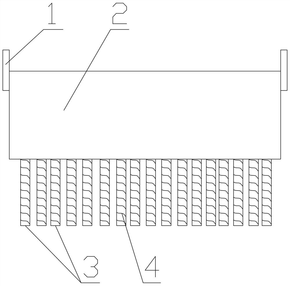
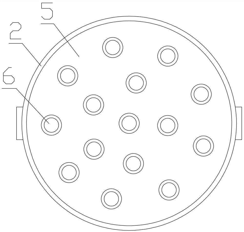
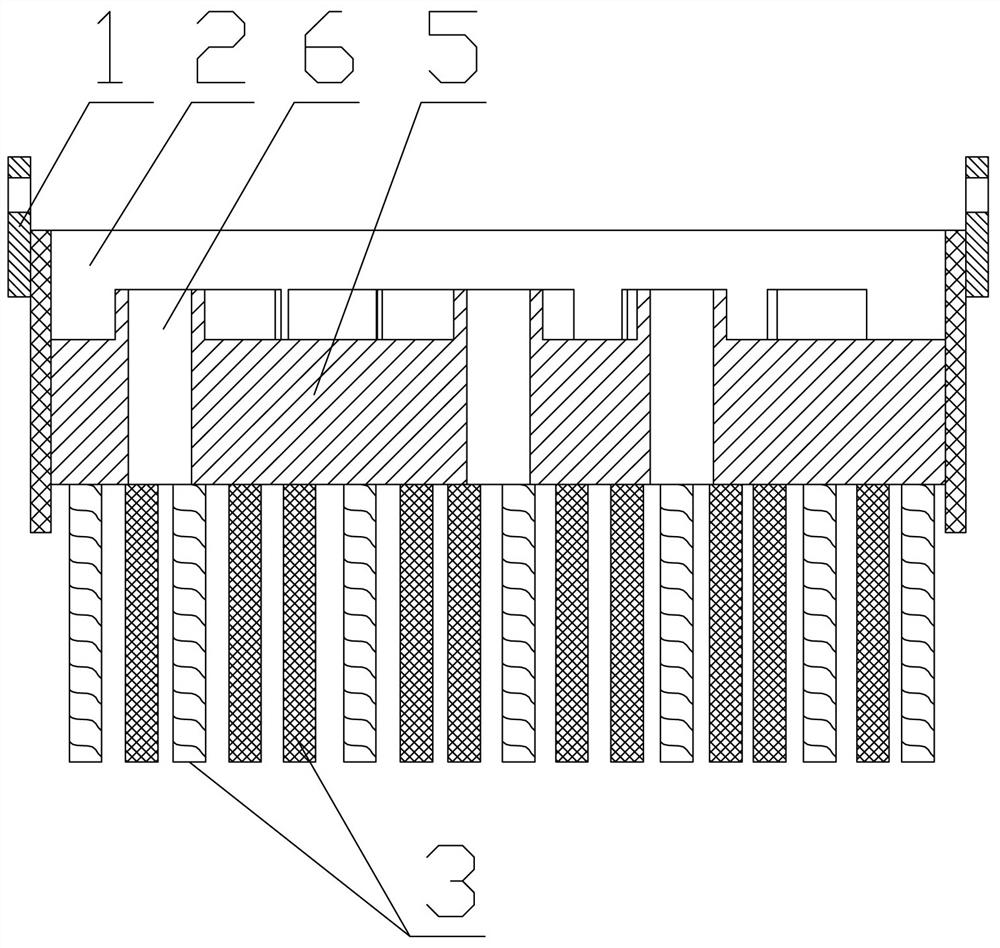
The invention relates to a rapid slag ladling device for molten steel in a steel ladle. The rapid slag ladling device is provided with a slag ladling barrel body, the upper surface and the lower surface of the slag ladling barrel body are provided with openings, hoisting lug plates are arranged at the symmetrical positions of the side wall of the upper end of the slag ladling barrel body, a slag ladling tray is arranged in the slag ladling barrel body and divides the interior of the slag ladling barrel body into an upper part and a lower part, the height of the upper bottom surface of the slagladling tray is lower than the height of the upper end surface of the slag ladling barrel body, a plurality of slag overflow hole pipes are arranged in the slag ladling tray in a penetrating and inserted mode, upper ports of the slag overflow hole pipes are higher than the upper bottom surface of the slag ladling tray, lower ports of the slag overflow hole pipes penetrate through the lower bottomsurface of the slag ladling tray, and a plurality of small slag suction steel columns are downwards arranged on the lower bottom surface of the slag ladling tray. The rapid slag ladling device has the advantages that by designing a completely novel slag removal tool for a steel ladle, the slag impurity removal efficiency of the molten steel in the whole steel ladle is greatly improved, the wholedevice is very simple in structural design, and compared with traditional slag removal treatment, the rapid slag ladling device is safer and more efficient in operation and very obvious in actual useeffect.

Description

technical field [0001] The invention relates to the technical field of metal smelting tools and equipment, in particular to a ladle molten steel rapid ladle slag device. Background technique [0002] In the iron and steel smelting industry, the molten steel is usually transferred through the ladle. The molten steel usually cleans the scum on the upper layer of the molten steel in the ladle. At present, many smelting factories use cranes to lift the ladle and tilt it at a certain angle. After being placed on an incline, the scum and impurities with low density on the upper layer of molten steel will flow down to achieve the purpose of slag removal. Due to the large size and weight of the ladle and the high temperature of molten steel, this operation method has great potential safety hazards , the operation time is still relatively long, and the slag removal is not thorough enough, and even a certain amount of molten steel will be poured out when dumping, resulting in waste. T...

Claims


Application Information

Patent Timeline
IPC IPC(8): B22D43/00
CPCB22D43/007
Inventor 潘文福刘海松胡定分刘俊张开强胡开波胡开发罗雄
Owner 湖北楠田工模具科技有限公司
Why Eureka
Try Eureka