Al technical title is built by PatSnap Al team. It summarizes the technical point description of the patent document.
A technology for wood and planing, applied in the field of planers for furniture wood, can solve the problems of low production efficiency, heavy workload of operators, poor practicability, etc., and achieve the effect of improving practicability and reducing workload
Inactive Publication Date: 2021-03-30
山东珍木园家居有限公司
View PDF0 Cites 1 Cited by
Summary
Abstract
Description
Claims
Application Information
AI Technical Summary
This helps you quickly interpret patents by identifying the three key elements:
Problems solved by technology
Method used
Benefits of technology
Problems solved by technology
[0002] Planer for furniture wood is a kind of auxiliary device for processing the plane of wood, which has been widely used in the field of furniture wood processing; an existing planer for furniture wood includes base, mounting plate, rotary planer , front table, rear table and guide plate, the bottom of the mounting plate is connected with the top of the base, the rotary planer is rotated and installed on the mounting plate, the bottom of the front table is connected with the top of the mounting plate, and the front table is located on the top of the rotary planer The bottom end of the rear workbench is connected with the top of the mounting plate, the rear workbench is located on the left side of the rotary planer, the bottom end of the guide plate is connected with the top of the front workbench and the rear workbench; an existing furniture wood When using a planer, first place the wood on the front workbench, make the wood stick to the guide plate, and then push the wood along the guide plate in the direction of the rear workbench, so that the rotating rotary planer can process the lower surface of the wood; During the use of a planer for furniture wood, it was found that during processing, it is necessary to manually push the wood forward, and at the same time press the wood to make the wood subsidize the top of the front workbench and the rear workbench. The workload of the operator is large, resulting in low production efficiency. low, less practical
Method used
Image
Click on the blue label to locate the original text in one second.
Reading with bidirectional positioning of images and text.
Examples
Embodiment Construction
[0017] The specific implementation manners of the present invention will be further described in detail below in conjunction with the accompanying drawings and embodiments. The following examples are used to illustrate the present invention, but are not intended to limit the scope of the present invention.
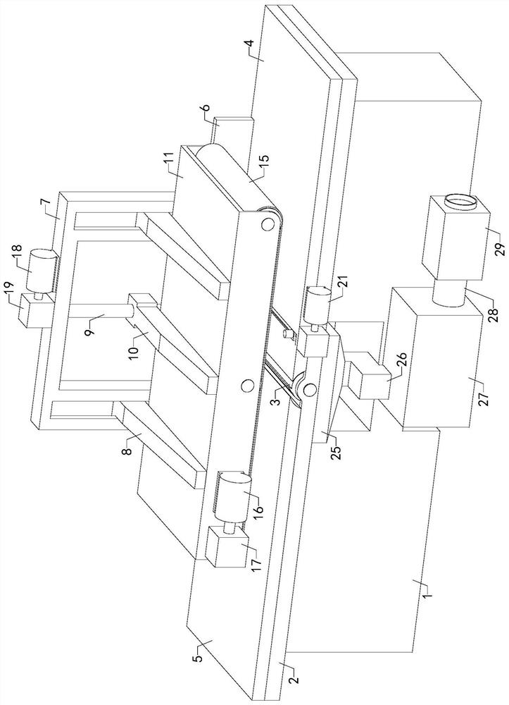
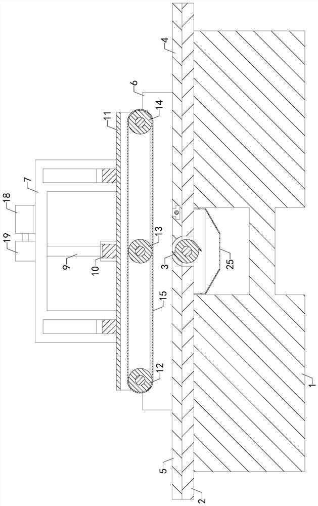
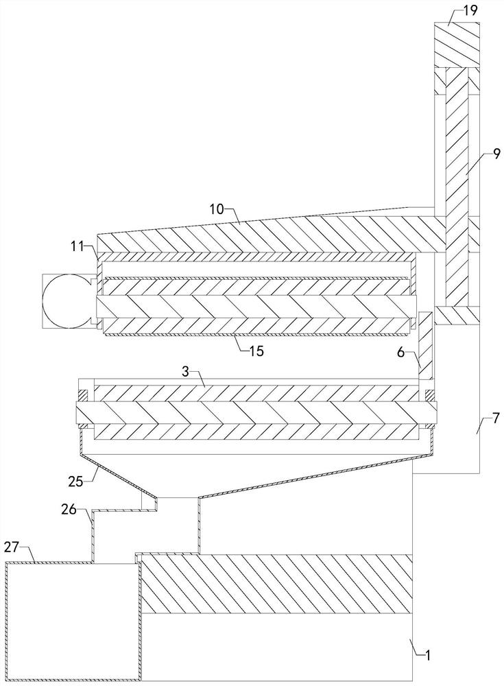
[0018] Such as Figure 1 to Figure 5 As shown, a kind of planer for furniture wood of the present invention comprises a base 1, a mounting plate 2, a rotary planer 3, a front table 4, a rear table 5 and a guide plate 6, the bottom of the mounting plate 2 and the top of the base 1 connection, the rotary planer 3 is rotated and installed on the mounting plate 2, the bottom end of the front table 4 is connected to the top of the mounting plate 2, the front table 4 is located on the right side of the rotary planer 3, and the bottom end of the rear table 5 is connected to the mounting plate The top of 2 is connected, and the rear table 5 is located on the left side of the rota...
PUM
Abstract
The invention relates to the technical field of furniture wood processing, in particular to a planing machine for furniture wood. According to the machine, a lifting support is enabled to move downwards by rotating a first lead screw and through threaded transmission, a mounting seat is driven to move downwards to enable a conveying belt to press the wood placed at the top end of a front workbench, a first motor is turned on, by means of transmission of a first speed reducer, a first roller and the conveying belt are driven to rotate, and the conveying belt conveys the wood, so that the workload of operators is reduced, and the practicability is improved. The machine comprises a base, a mounting plate, a rotary planer tool, the front workbench, a rear workbench and a guide plate; and the device further comprises a pressing support, two sets of sliding supports, the first lead screw, the lifting support, the mounting seat, the first roller, a second roller, a third roller, the conveyingbelt, the first motor and the first speed reducer, wherein the pressing support is mounted at the rear end of the base, and two sets of sliding rails are arranged on the pressing support.
Description
technical field [0001] The invention relates to the technical field of furniture wood processing, in particular to a planer for furniture wood. Background technique [0002] Planer for furniture wood is a kind of auxiliary device for processing the plane of wood, which has been widely used in the field of furniture wood processing; an existing planer for furniture wood includes base, mounting plate, rotary planer , front table, rear table and guide plate, the bottom of the mounting plate is connected with the top of the base, the rotary planer is rotated and installed on the mounting plate, the bottom of the front table is connected with the top of the mounting plate, and the front table is located on the top of the rotary planer The bottom end of the rear workbench is connected with the top of the mounting plate, the rear workbench is located on the left side of the rotary planer, the bottom end of the guide plate is connected with the top of the front workbench and the rea...
Claims
Application Information
Patent Timeline
Application Date:The date an application was filed.
Publication Date:The date a patent or application was officially published.
First Publication Date:The earliest publication date of a patent with the same application number.
Issue Date:Publication date of the patent grant document.
PCT Entry Date:The Entry date of PCT National Phase.
Estimated Expiry Date:The statutory expiry date of a patent right according to the Patent Law, and it is the longest term of protection that the patent right can achieve without the termination of the patent right due to other reasons(Term extension factor has been taken into account ).
Invalid Date:Actual expiry date is based on effective date or publication date of legal transaction data of invalid patent.