
Magnetic levitation UHPC box girder

A magnetic levitation and box girder technology, applied in bridges, roads, tracks, etc., can solve the problems of adding dampers, difficult to meet the requirements of natural vibration frequency, and high cost of steel structure, so as to prevent warping and instability, save engineering cost, and reduce the cost of construction. beam light effect

Pending Publication Date: 2021-03-30
CHINA RAILWAY SIYUAN SURVEY & DESIGN GRP
View PDF0 Cites 1 Cited by
  • Summary
  • Abstract
  • Description
  • Claims
  • Application Information

AI Technical Summary

Problems solved by technology

When the span increases, conventional concrete structures cannot meet the stringent deformation requirements of high-speed maglev bridge structures due to their own characteristics such as shrinkage and creep, while the cost of steel structures is high, and the natural frequency is difficult to meet the requirements. At the same time, it may be necessary Additional damper

Method used


Image

  • Magnetic levitation UHPC box girder
  • Magnetic levitation UHPC box girder
  • Magnetic levitation UHPC box girder

Examples


Embodiment Construction

[0027] In order to make the object, technical solution and advantages of the present invention clearer, the present invention will be further described in detail below in conjunction with the accompanying drawings and embodiments. It should be understood that the specific embodiments described here are only used to explain the present invention, not to limit the present invention. In addition, the technical features involved in the various embodiments of the present invention described below can be combined with each other as long as they do not constitute a conflict with each other.

[0028] In describing the present invention, it is to be understood that the terms "center", "longitudinal", "transverse", "length", "width", "thickness", "upper", "lower", "front", " Back", "Left", "Right", "Vertical", "Horizontal", "Top", "Bottom", "Inner", "Outer", "Clockwise", "Counterclockwise", "Axial", The orientation or positional relationship indicated by "radial", "circumferential", et...


PUM


Abstract

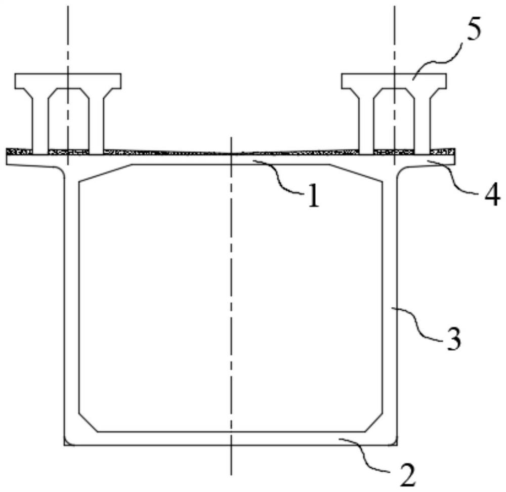
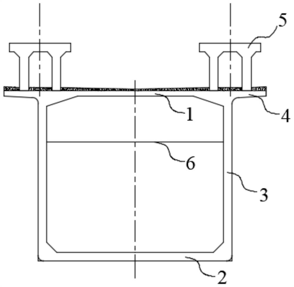
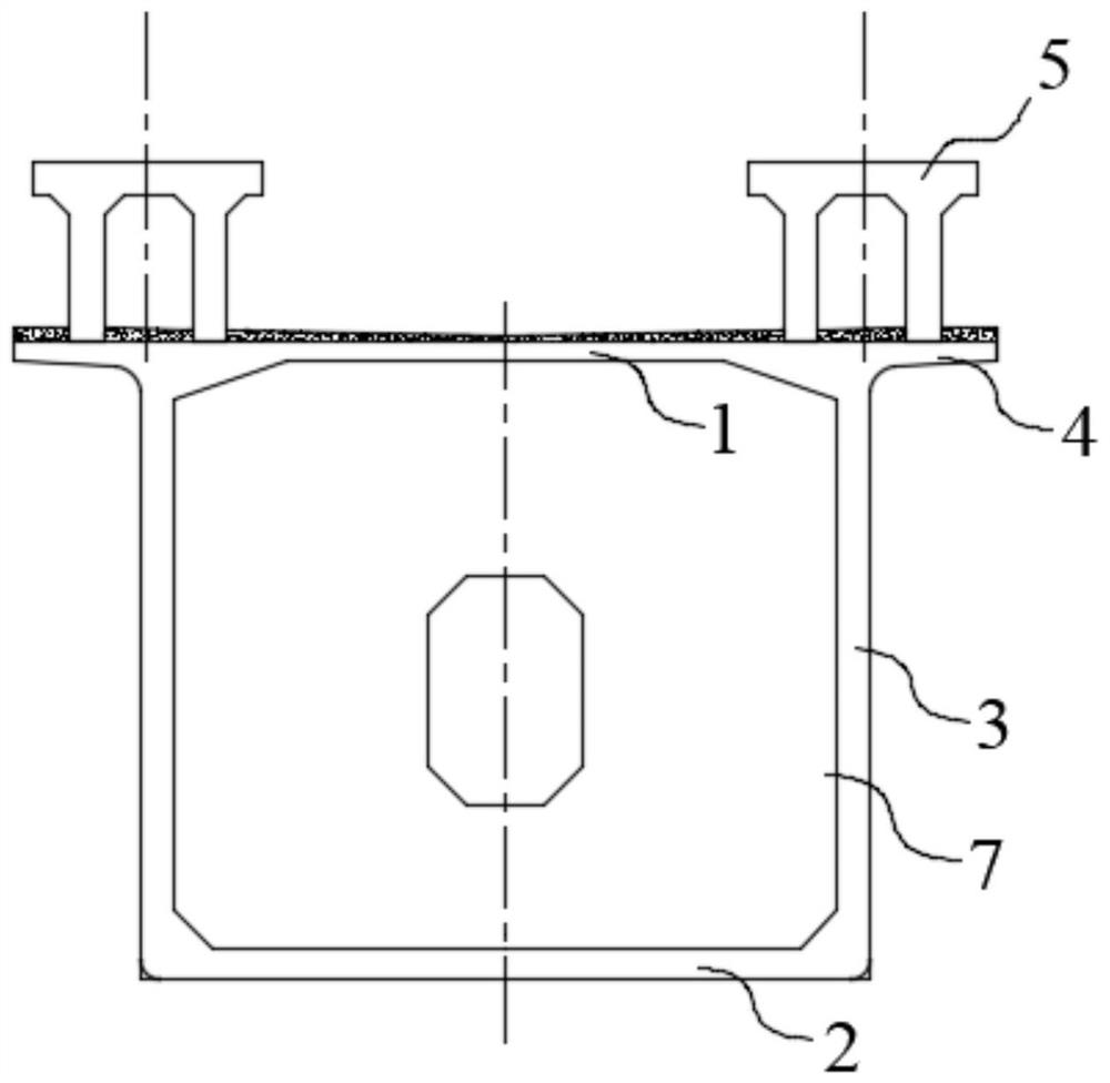
The invention discloses a magnetic levitation UHPC box girder. The box girder comprises a box girder top plate, a box girder bottom plate and a box girder web arranged between the box girder top plateand the box girder bottom plate; box girder transverse ribs are arranged between the box girder webs in the transverse direction at intervals, the top of each box girder transverse rib is fixedly connected with the box girder top plate, the two transverse ends of each box girder transverse rib are fixedly connected with the inner sides of the box girder webs respectively, and the box girder transverse ribs are located in a pressed area of the box girder top plate to prevent warping instability of a thin plate; the box girder top plate, the box girder bottom plate and the box girder web are all made of UHPC materials so that the beam height and thicknesses of the box girder top plate, the box girder bottom plate and the web are reduced. The box girder is suitable for maglev transportation,the top plate, the bottom plate and the web of the box girder are made of UHPC materials, meanwhile, thicknesses of the top plate, the bottom plate and the web of the box girder are reduced, rigidityis improved, the strict deformation requirement of high-speed maglev for a bridge structure is met, meanwhile, the section square amount is reduced, construction is convenient, and the use amount ofa lower structure is reduced; the transverse ribs and the transverse partition plates are made of common concrete, so the structure cost is reduced.

Description

technical field [0001] The invention belongs to the technical field of maglev rail transit, and more specifically relates to a maglev UHPC box girder. Background technique [0002] Maglev transportation is a kind of ground passenger transportation. The significant difference from the traditional wheel-rail transportation system is that the car body is suspended above the track by means of suspension force, and its walking part does not contact the track. The propulsion generated by the linear induction motor moves forward on the track. The charged levitation electromagnet on the levitation frame of the high-speed maglev train and the long stator coil on the track attract each other to provide the levitation force for the train to lift the train upward, and ensure a stable levitation gap by controlling the levitation excitation current. The suspension gap between the electromagnet and the track is generally controlled at about 10mm. [0003] The charged guiding electromagne...

Claims


Application Information

Patent Timeline
Patent Type & Authority Applications(China)
IPC IPC(8): E01B25/30E01B1/00E01D2/04
CPCE01B1/002E01B25/30E01D2/04
Inventor 曾敏文望青周天喜严爱国胡方杰王志平曹文杰夏正春张玲杨光杨朝龙林骋
Owner CHINA RAILWAY SIYUAN SURVEY & DESIGN GRP
Learn More