
An Improved Pavement Structure Depth Detection Device

A technology of pavement structure depth and detection device, which is applied to measurement devices, optical devices, instruments, etc., can solve the problems of inability to lay, affect the laying area, and inaccurate testing, so as to improve the test accuracy, facilitate the measurement of the area, and avoid the occurrence of effect of error

Active Publication Date: 2022-04-12
黑龙江东北林大工程检测有限公司
View PDF15 Cites 0 Cited by
  • Summary
  • Abstract
  • Description
  • Claims
  • Application Information

AI Technical Summary

Problems solved by technology

It refers to the average depth of the uneven opening pores on a certain area of ​​the road surface. It is mainly used to evaluate the macroscopic roughness, drainage performance and skid resistance of the road surface. The manual sanding method is to spread fine sand on the road surface and calculate the embedded unevenness. The ratio of the volume of the sand in the gaps on the uneven surface to the coverage area is used to obtain the depth of the structure. This is the most basic and commonly used method in engineering. The test method: spread a known volume of sand on the road surface to be tested At the measuring point, measure the area covered by flattening, and the ratio of the volume of sand to the average area covered is the depth of the structure. The disadvantage of this method is that it is impossible to lay a better circle, and the difference in downforce will affect the depth of the structure. In addition, the measurement process requires sufficient cleaning and wall ventilation of the measurement area to prevent external factors from affecting the measurement accuracy

Method used

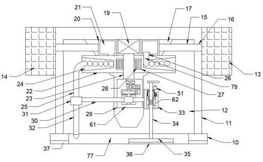

Image

  • An Improved Pavement Structure Depth Detection Device
  • An Improved Pavement Structure Depth Detection Device
  • An Improved Pavement Structure Depth Detection Device

Examples


Embodiment Construction

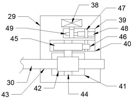
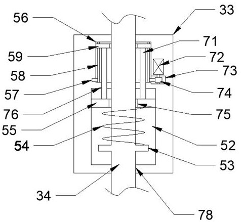
[0019] Combine below Figure 1-3 The present invention is described in detail, wherein, for the convenience of description, the orientations mentioned below are defined as follows: figure 1 The up, down, left, right, front and back directions of the projection relationship itself are the same.

[0020] An improved road surface structure depth detection device described in conjunction with accompanying drawings 1-3 includes a bottom ring 10, a passing groove 77 is provided in the middle of the bottom ring 10, and a windshield barrel 11 is fixed on the upper side of the bottom ring 10 , the lower side of the bottom ring 10 is fixed with a first anti-slip pad 37, the middle of the windshield barrel 11 is provided with an activity chamber 12 with an opening downward, and the rear side of the upper side wall of the activity chamber 12 is fixed with a sand storage body 17, the sand storage body 17 is provided with a storage chamber, the lower side of the sand storage body 17 is pro...


PUM


Abstract

The invention discloses an improved road surface structure depth detection device, which comprises a bottom ring, a passage groove is arranged in the middle of the bottom ring, a windshield barrel is fixed on the upper side of the bottom ring, and a windshield bucket is fixed on the lower side of the bottom ring. There is a first anti-slip pad, and the middle of the windshield barrel is provided with an activity chamber with an opening downward, and the rear side of the upper side wall of the activity chamber is fixed with a sand storage body. Using this device, the device can rotate around the center by setting The push plate, and the rotation diameter of the push plate can be controlled to realize the flat spreading of the tested sand, and the shape of this way of laying is relatively regular, which is convenient for measuring the area and has good accuracy.

Description

technical field [0001] The invention relates to an improved pavement structure depth detection device, and mainly relates to the field of building measurement equipment. Background technique [0002] Pavement texture depth, formerly known as texture depth, is an important indicator of pavement roughness. It refers to the average depth of the uneven opening pores on a certain area of ​​the road surface. It is mainly used to evaluate the macroscopic roughness, drainage performance and skid resistance of the road surface. The manual sanding method is to spread fine sand on the road surface and calculate the embedded unevenness. The ratio of the volume of the sand in the gaps on the uneven surface to the coverage area is used to obtain the depth of the structure. This is the most basic and commonly used method in engineering. The test method: spread a known volume of sand on the road surface to be tested At the measuring point, measure the area covered by flattening, and the ra...

Claims


Application Information

Patent Timeline
Patent Type & Authority Patents(China)
IPC IPC(8): G01B11/22
CPCG01B11/22
Inventor 范刘盛
Owner 黑龙江东北林大工程检测有限公司
Learn More