
Wireless power transmission collector ring with compact structure

A technology of wireless power transmission and compact structure, applied in the field of energy transmission, can solve the problems of large overall structure size, complex mechanical structure, unsuitable use scenarios with limited space requirements, etc., to ensure structural strength and installation position, The effect of simplifying the mechanical structure

Pending Publication Date: 2021-03-30
成都天通电子科技有限公司
View PDF0 Cites 0 Cited by
  • Summary
  • Abstract
  • Description
  • Claims
  • Application Information

AI Technical Summary

Problems solved by technology

[0004] The wireless power transmission bus ring is based on the principle of electromagnetic induction, and realizes power transmission through the electromagnetic induction of the inner and outer windings. The inner ring group is the rotor, and the outer ring group is the stator. There is no contact between the rotor and the stator, which solves the problem of the traditional brush bus ring. There is no problem of wear and tear, there will be no phenomenon such as poor contact, and there is no need to replace the brushes, thereby improving the reliability of the turntable; but the existing wireless transmission bus ring has a large overall structure due to its complicated mechanical structure, which is not suitable for Use scenarios with limited space requirements

Method used


Image

  • Wireless power transmission collector ring with compact structure
  • Wireless power transmission collector ring with compact structure
  • Wireless power transmission collector ring with compact structure

Examples


Embodiment Construction

[0030] Exemplary embodiments of the present disclosure will be described in more detail below with reference to the accompanying drawings. Although exemplary embodiments of the present disclosure are shown in the drawings, it should be understood that the present disclosure may be embodied in various forms and should not be limited by the embodiments set forth herein. Rather, these embodiments are provided for more thorough understanding of the present disclosure and to fully convey the scope of the present disclosure to those skilled in the art. It should be noted that, in the case of no conflict, the embodiments of the present invention and the features in the embodiments can be combined with each other. The present invention will be described in detail below with reference to the accompanying drawings and examples.

[0031] In the description of the present invention, it should be noted that the orientation or positional relationship indicated by the terms "inner", "outer"...


PUM


Abstract

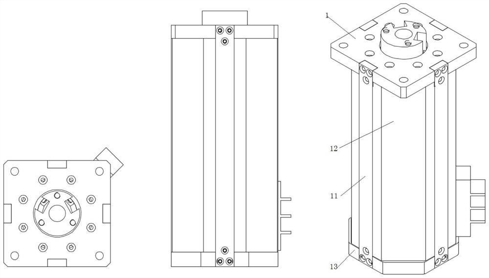
The invention provides a wireless power transmission collector ring with a compact structure, which comprises an outer surrounding group, an inner surrounding group and a shielding cover, and is characterized in that the inner surrounding group and the outer surrounding group are arranged in the shielding cover and are used for shielding a generated magnetic field from the outside; the shielding cover is formed by circumferentially and uniformly distributing a plurality of detachable split shielding pieces, the split shielding pieces are combined and butted through side edge fixing pieces, andthe shielding cover is of a polyhedral structure formed by butting and combining the plurality of split shielding pieces so as to save space. The inner winding and the outer winding are wrapped by the aluminum cavity, sufficient structural strength is guaranteed, and magnetic field coupling between the inner winding and the outer winding is kept while magnetic fields of the inner winding and theouter winding are shielded; and the cage type structural design is adopted, the mechanical structure is simplified, and the structural strength and the design of the installation position are guaranteed.

Description

technical field [0001] The invention relates to the technical field of energy transmission, in particular to a compact wireless transmission bus ring. Background technique [0002] Slip rings are widely used in aerospace, aviation, navigation, medical and various precision instrument fields, and are the core components of high-precision turntables. Its function is to realize the transmission of electric power or electric signal between two relatively continuous rotating parts, and avoid the winding and twisting of wires during relative rotation. [0003] Collector rings are also called collector rings, conductive rings, slip rings, collector rings, etc. It can be used in any electromechanical system that requires continuous rotation while transmitting power and signals from a fixed position to a rotating position. Slip rings can improve system performance, simplify system structure, and prevent wires from being twisted during rotation. [0004] The wireless power transmis...

Claims


Application Information

Patent Timeline
Patent Type & Authority Applications(China)
IPC IPC(8): H02J50/10H02J50/70H01F38/14H01F27/36H01F27/30
CPCH01F27/2885H01F27/306H01F38/14H02J50/10H02J50/70H02J50/005
Inventor 史太一许建平何激扬张鸿
Owner 成都天通电子科技有限公司
Learn More